 홀
홀
![]()
![]()
![]()
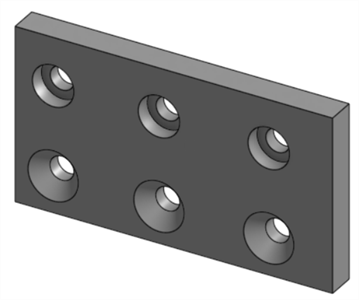
스케치 점, 원 중심 및 메이트 커넥터에 간단한 카운터싱크 구멍, 카운터보어 구멍을 만들 수 있습니다.
Onshape에는 두 가지 방법으로 홀을 만들 수 있습니다. 첫 번째 방법은 제거 탭을 사용하여 스케치와 돌출 피처를 사용하여 홀을 생성하는 것입니다. 두 번째는 홀 피처 활용입니다. 각 방법에는 장점과 단점이 있습니다.
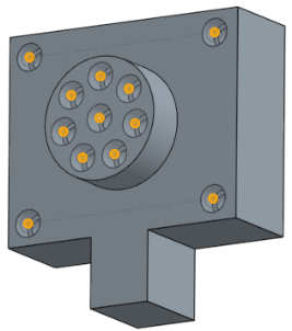
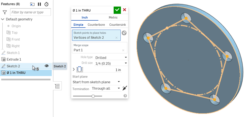
홀 피처는 선택한 스케치 점에 구멍을 배치하여 홀의 중심을 점에 맞춰 정렬합니다. 허용되는 스케치 점에는 독립점, 꼭지점 및 원의 중심점이 포함됩니다. 모든 비구성 꼭지점을 포함하려면 피처 목록에서 스케치를 선택합니다.
암시적 메이트 커넥터와 명시적 메이트 커넥터를 활용하여 홀의 위치를 제어할 수도 있습니다. 암시적 메이트 커넥터를 홀의 중심점으로 선택하려면 메이트 커넥터 선택 아이콘을 클릭하고 그래픽 영역에서 암시적 점 중 하나를 선택합니다. 선택적으로 파란색 선택 필드에 있는 메이트 커넥터 아이콘을 클릭하여 암시적 메이트 커넥터를 추가로 편집할 수 있습니다.
병합 범위 필드를 클릭하여 절단할 파트를 지정합니다.
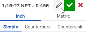
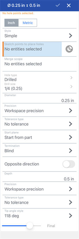
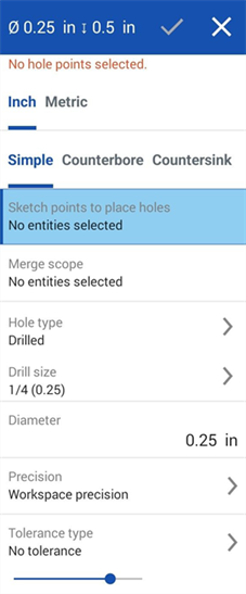
예를 들어, 브레이크 레버 피벗용 홀을 만듭니다. 피처 툴바에서 새 홀 피처를 시작합니다. 지표 탭을 선택합니다. 단순, 카운터보어 및 카운터싱크의 세 가지 홀 유형 탭도 사용할 수 있습니다.
드릴 홀 유형을 사용하여 단순 홀을 생성합니다. 다른 홀 유형으로는 여유 값, 탭 및 PEM® 이 있습니다. 드릴된 홀을 사용하여 드릴 크기를 지정하고 필요한 경우 지름을 편집할 수 있습니다. 여유 값, 탭 및 PEM® 홀을 사용하면 각 홀 유형에 따라 추가 필드를 사용하여 추가로 사용자 지정할 수 있습니다.
홀의 시작 면과 종료를 모두 설정합니다. 기본적으로 홀은 파트에서 시작됩니다. 대체 시작 평면을 지정하려면 스케치 평면에서 시작 또는 선택한 평면에서 시작을 선택합니다.
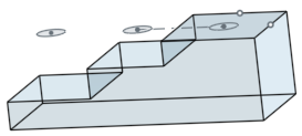
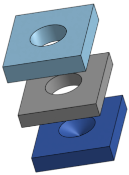
예를 들어 이 계단식 파트에 몇 개의 홀 컷을 만들어 보겠습니다. 처음에는 스케치가 중심 계단의 면에 위치합니다. 파트에서 시작을 시작 옵션으로 사용하면 처음 두 단계에서 홀이 선명하게 뚫립니다. 그러나 마지막 단계는 스케치 평면 위로 올라갑니다. 단면도를 보면 피처가 홀을 만들었지만 스케치 면 위를 관통하지 않는 것이 분명합니다. 파트에서 시작은 시작 면을 홀과 같은 방향으로만 조정합니다. 스케치 평면이 이미 파트와 교차하기 때문에 파트에서 시작과 스케치 평면에서 시작해도 동일한 결과가 나타납니다.
시작 옵션을 더 자세히 설명하기 위해 스케치를 상단 계단 위 1mm 평면으로 이동해 보겠습니다. 이제 간단한 홀로 세 단계를 모두 관통할 수 있습니다.
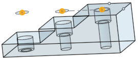
홀 유형을 크기가 M3인 카운터보어로 변경하고 파트에서 시작을 선택합니다. 홀 피처는 세 단계 모두에서 3mm의 전체 외부 깊이를 절단합니다.
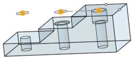
시작 평면을 스케치 평면에서 시작으로 변경합니다.이제 홀 중 하나에만 카운터보어가 있습니다. 자세히 살펴보면 카운터보어의 깊이는 파트에서 시작을 선택할 때 피처 컷팅으로 절단한 전체 3mm보다 작습니다. 이는 스케치 평면이 파트 표면에서 1mm 위에 있기 때문입니다.
선택한 평면에서 시작을 선택하고 상단 계단의 면을 홀 시작 평면으로 지정합니다. 카운터보어는 상단 단계에서 최대 깊이까지 절단됩니다.
브레이크 레버에서 스케치 1을 표시하고 큰 원의 중심점을 홀 위치로 선택합니다. 14mm 홀에 해당하는 드릴 크기를 14로 지정합니다. 파트에서 시작을 선택하면 스케치 평면의 위치 때문에 전체 파트에 홀이 뚫리지 않습니다. 이 문제를 해결하려면 시작 평면을 선택한 평면에서 시작으로 변경하고 외부 면을 선택합니다.
또 다른 방법은 암시적 메이트 커넥터를 사용하는 것입니다. 이렇게 하려면 스케치 1을 숨기고 "메이트 커넥터 선택"을 클릭합니다. 그런 다음 외부 면에서 암시적 메이트 커넥터를 선택합니다.
이 예제에는 파트가 하나뿐이므로 병합 범위가 자동으로 채워집니다.
마지막으로, 홀의 종료를 설정합니다. 전체 관통은 병합 범위 내의 모든 파트에 홀을 뚫습니다. 단방향은 지정된 치수에서 홀을 종료합니다.
다음까지는 홀 끝으로부터의 선택적 오프셋을 사용하여 다음 면 또는 만나는 면까지 절단합니다. 반대 방향 화살표를 토글하여 오프셋을 반전시킵니다.
엔티티까지는 면이나 면과 같은 선택한 요소까지 잘라냅니다. 이 옵션을 사용하면 전체 지름이 요소까지 절단됩니다. 홀의 팁 각도 스타일이 평평하지 않은 경우 팁은 선택한 요소를 지나 확장됩니다. 팁으로부터의 오프셋을 사용하면 홀 컷을 편집하여 팁 침입을 방지하거나 홀 컷을 확장할 수 있습니다.
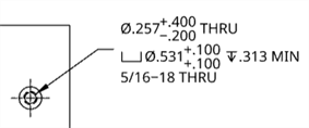
또한 직경 및 깊이 공차 컨트롤을 확장하여 홀 설명선의 공차 및 정밀도를 사용자 지정할 수 있습니다. 카운터보어 및 카운터싱크 홀에 대해 더 많은 공차 제어를 사용할 수 있습니다.
돌출 컷에 비해 홀 피처의 장점 중 하나는 도면을 작성할 때 분명하게 드러납니다. 홀 설명선 주석은 홀 피처로 생성한 홀에만 추가할 수 있습니다. 홀 설명선은 돌출된 컷에 첨부되지 않습니다.
표준 콘텐츠를 어셈블리 내에 배치할 때 얻을 수 있는 또 다른 이점이 있습니다. 자동 크기 조정 기능은 하드웨어 또는 조임쇠의 크기를 자동으로 조정할 때 지름과 스레드 사양을 결정합니다. 자동 크기 조정은 돌출 제거 기능을 사용하여 길이 또는 스레드 길이를 감지할 수 없습니다.
- 스케치 포인트로 스케치를 만든 다음 피처 툴바에서 구멍 피처 아이콘 (
 ) 을 클릭합니다.
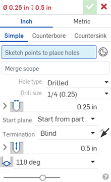
-
측정값 (인치 또는 미터) 을 선택합니다.
- 홀 스타일을 선택합니다.
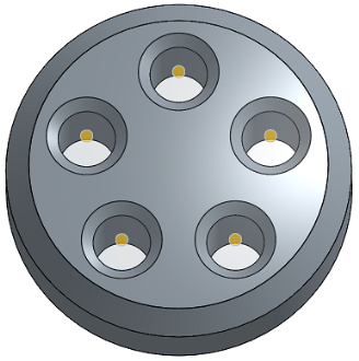
- Simple - A uniform-diameter drilled hole.
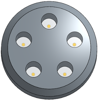
- Counterbore - A cylindrical flat-bottomed drilled hole that enlarges another coaxial drilled hole.
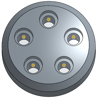
- Countersink - A drilled hole with a conical relief at the top.
- 스케치에서 구멍 중심을 배치할 점 (형상의 모서리, 선 끝, 스플라인 점, 원 중심 등 포함) 을 선택합니다.
- 여러 점을 상자 형식으로 선택할 수 있습니다.
- 메이트 커넥터 아이콘(
 )을 클릭하여 암시적 메이트 커넥터를 스케치 점 대신 점으로 선택하거나 만들 수 있습니다.
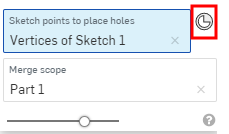
메이트 커넥터를 선택한 후 메이트 커넥터 아이콘(
)을 클릭하여 메이트 커넥터를 편집할 수 있는 대화상자를 엽니다.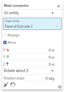
- 또는 스케치를 클릭하여구성 형상으로사용된 점을 제외한 모든 점을 스케치에서 자동으로 선택합니다.
- 병합 범위필드에 초점을 맞추고 홀을 포함할 파트를 선택합니다.
- 다음 구멍 유형 및 구멍 유형 사양 중에서 필요에 맞는 것을 선택하십시오.모든 구멍 유형에서 모든 구멍 유형 사양을 사용할 수 있는 것은 아니며 선택 사항에 따라 달라집니다.
- Drilled - Creates a drilled hole.
- Drill size - Select a Drill size from the dropdown list.
- Clearance - Creates a clearance hole.
- Size - Select a Clearance size from the dropdown list.
- Fastener fit - Select from Close, Free, Close (ASME), Normal (ASME), Loose (ASME)
- 탭 - 탭 구멍을 만듭니다.
코스메틱 스레드는 형상에 영향을 미치지 않는 스레드의 시각적 표현입니다. Onshape는 Part Studio에서 외부 스레드와 탭 구멍에 대한 코스메틱 스레드를 표시합니다. 이를 통해 스레드 형상을 다시 계산할 필요가 없으므로 반복 및 재생성 속도가 향상됩니다. 또한 홀/스레드 설명선을 사용하여 도면에 코스메틱 스레드에 주석을 달 수 있습니다.
- 탭 유형 - 직선 탭 , 직선 파이프 탭 (미터식 전용) 또는테이퍼 파이프 탭을 선택합니다. 아래 옵션은 여기서 선택한 항목에 따라 달라집니다.
- 스레드 유형 - (직선 파이프 탭에만 사용 가능)영국 표준 파이프 평행 (BSPP) 스레드의 경우G를 선택하고 영국 표준 병렬 내부 스레드 (테이퍼 외부 스레드와 결합할 때 사용) 의 경우RP를 선택합니다.
- Size - Select a tapped hole size from the dropdown list.
- Threads/inch - Select the number of threads per inch (tpi) setting from the dropdown list.
- 패스너 맞춤 - 병합 범위 필드에서 두 개 이상의 파트를 선택한 경우 직선 탭 유형에만 사용할 수 있습니다. 없음, 닫힘, 자유, 닫힘(ASME), 수직(ASME), 느슨함(ASME) 중에서 선택합니다.
- 스레드 클래스 - 선택적으로 확인란을 선택하여 스레드 클래스를 켜거나 끌 수 있습니다.켜면 드롭다운에서 적절한 인치 또는 미터 클래스를 사용할 수 있습니다.
- PEM® - PennEngineering® fasteners. This option is not available for counterbored or countersunk holes.
- Fastener - Select from Self-clinching nuts, Self-clinching standoffs, Self-clinghing studs & pins
- Fastener type - Select from S™/SS™/CLS™/CLSS™/SP™ nuts, CLA™ free running locknuts, S-RT™ Free-running locknuts, SL™ TRI-DENT® Prevailing torque locknuts, Self-clinching nuts, H™ Nuts/HNL™ Prevailing torque locknuts, SH™ Hard panel nuts, SMPS™/SMPP™ Nuts.
- Size - Select a tapped hole size from the dropdown list.
- Fastener fit - Clearance.
- Drilled - Creates a drilled hole.
- 구멍의 지름 공차 컨트롤을 입력합니다.
- Diameter - Enter a diameter value for the hole.
- Precision - Select a precision for the hole, either Workspace precision or another precision value from the dropdown list.
- Tolerance type - Select a tolerance type for the hole from the dropdown list. Options are No tolerance, Symmetrical, Deviation, Limits, Min, Max, Fit, Fit with tolerance, Fit (tolerance only).
- Deviation - Available for the Symmetrical Tolerance type. Enter a deviation value.
- Upper - Available for the Deviation, Limits, Fit tolerance, Fit with tolerance, and Fit (tolerance only) Tolerance types. Tolerance type. Enter the upper tolerance value.
- Lower -Deviation, Limits, Fit tolerance, Fit with tolerance, and Fit (tolerance only) Tolerance types. Enter the lower tolerance value.
- Standard - Available for the Fit Tolerance type. Select the ANSI or ISO standard from the dropdown list.
- Fit type - Available for the Fit Tolerance type. Select User defined, Clearance, Transition, or Interference from the dropdown list.
- Hole class - Available for the Fit tolerance, Fit with tolerance, and Fit (tolerance only) Tolerance types. Select H5, H6, H7, H8, H9, H10, H11 from the dropdown list.
- Shaft class - Available for the Fit tolerance, Fit with tolerance, and Fit (tolerance only) Tolerance types when the ISO Standard is selected. Select a Shaft class from the dropdown list.
- 구멍의 시작 평면을 선택합니다.
- Start from part - the hole begins from the part face.
- Start from sketch plane - The hole begins from the sketch plane.
- Start from selected plane - The hole begins from a selected plane.
- Hole start plane or mate connector - Select the entity (plane or mate connector) from which the hole begins.
이 옵션을 사용하면 홀이 서로 다른 높이에서 시작될 때 파트의 동일한 위치에서 깊이 끝을 제어할 수 있습니다.예를 들어, 홀의 모든 스케치 점이 한 평면에 있습니다.
깊이가 1인치인 카운터보어 홀의 경우, 홀이 스케치 면에서 시작하지 않을 때 더 짧은 홀에는 카운터보어만 포함되고, 가장 깊은 홀에는 카운터보어와 볼트 샤프트가 포함됩니다.
그러나 홀이 스케치 면에서 시작하는 경우, 먼저 샤프트가 배치되고 카운터보어가 단축됩니다.
동일한 시나리오가 카운터싱크 홀에도 적용됩니다. 단순 홀은 깊이에 대해서만 조정됩니다.
- 해지 (종료) 조건을 선택합니다.모든 종료 종료 조건의 경우 반대 방향 화살표 (
 ) 를 클릭하여 구멍 방향을 반전시킵니다.
- Blind - The hole ends at a specified depth in the selected part.
- Depth - Enter the depth value for the hole, inclusive of the counterbore or countersink depth.
- Precision - Select a precision for the hole depth, either Workspace precision or another precision value from the dropdown list.
- Tolerance type - Select a tolerance type for the hole from the dropdown list. Options are No tolerance, Symmetrical, Deviation, Limits, Min, and Max.
- Deviation - Available for the Symmetrical Tolerance type. Enter a deviation value.
- Upper - Available for the Deviation, Limits, Fit tolerance, Fit with tolerance, and Fit (tolerance only) Tolerance types. Tolerance type. Enter the upper tolerance value.
- Lower -Deviation, Limits, Fit tolerance, Fit with tolerance, and Fit (tolerance only) Tolerance types. Enter the lower tolerance value.
- Counterbore diameter - For counterbore holes, enter the diameter value for the hole tip, as well as Precision and Tolerance controls, which are the same as those found above, under Blind > Depth.
- Counterbore depth - For counterbore holes, enter the depth value of the enlarged hole, as well as Precision and Tolerance controls, which are the same as those found above, under Blind > Depth.
- Countersink diameter - For countersink holes, enter the diameter value of the enlarged hole, as well as Precision and Tolerance controls, which are the same as those found above, under Blind > Depth.
- Countersink angle - For countersink holes, enter the angle value of the hole, as well as Precision and Tolerance controls, which are the same as those found above, under Blind > Depth.
- Tapped depth - For tapped holes, the full thread depth of a tapped hole, in document units (or specify other units). Precision and Tolerance type controls have the same options as listed above, under the Depth tolerance controls.
- Tap clearance - For blind tapped holes, the number of thread pitch lengths between the bottom of the Tapped depth and bottom of the hole.
한계 또는 편차 공차 유형을 선택한 겨우, 하한 및 상한 경계에 대해 제로(0)와 음수 값이 허용됩니다. 계산된 하한 경계가 계산된 상한 경계보다 클 경우 오류가 발생합니다. 계산된 상한 및 하한 경계가 같을 수 있습니다.
- Depth - Enter the depth value for the hole, inclusive of the counterbore or countersink depth.
- Up to next - Up to the next face or faces encountered.
- Offset from tip - Check to enter an offset distance value from the hole tip. Click the Opposite direction arrow () to flip the offset.
- Depth - Multiple.
- Precision and Tolerance type controls - Same options as those found above, under Blind > Depth.
- Offset from tip - Check to enter an offset distance value from the hole tip. Click the Opposite direction arrow (
- Up to entity - Up to a selected entity or Mate connector.
- Up to entity or mate connector - Select the entity (for example, a face or plane) or Mate connector ().
- Offset from tip - Check to enter an offset distance value from the hole tip. Click the Opposite direction arrow () to flip the offset.
- Depth - Multiple.
- Precision and Tolerance type controls - Same options as those found above, under Blind > Depth.
- Up to entity or mate connector - Select the entity (for example, a face or plane) or Mate connector (
- Through all - Completely through the part(s) selected in the Merge scope.
- Tap through all - For tapped holes, keep checked to create thread for the full length of the hole. Uncheck to specify:
- Tapped depth - Enter a custom thread depth.
- Precision and Tolerance type controls - Same options as those found above, under Blind > Depth.
- Tap through all - For tapped holes, keep checked to create thread for the full length of the hole. Uncheck to specify:
- Blind - The hole ends at a specified depth in the selected part.
- 구멍의 팁 각도 스타일을 선택합니다.옵션은 118도, 135도, 플랫 또는 사용자 지정으로 사용자 지정할 수 있습니다.
- Tip angle - For custom holes, enter a Tip angle value.
- Precision and Tolerance type controls - Same options as those found above, under Blind > Depth.
- 구멍 피처의 이름은 구멍의 설정을 반영하여 자동으로 업데이트됩니다.
- 홀의 이름을 바꾸려면 홀 대화상자의 이름 필드를 마우스오버하고 나타나는 연필 아이콘을 클릭합니다. 새 이름을 입력한 다음 Enter 키를 누릅니다.
- 홀 이름을 자동 생성된 기본값으로 다시 변경하려면 홀 대화상자의 이름 필드 위에 마우스를 놓고 연필 아이콘을 클릭하고 이름 필드에서 모든 것을 삭제한 다음 Enter 키를 누릅니다.
- 체크마크 아이콘 (
 ) 을 클릭하여 구멍을 생성합니다.
일정 지름의 드릴 홀:
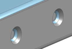
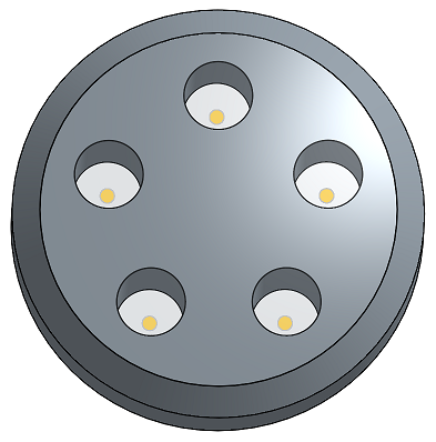
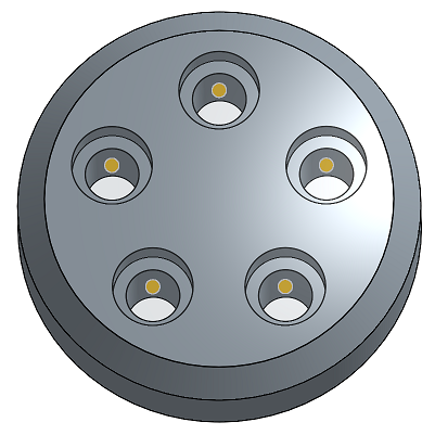
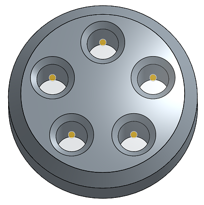
활성 금속 판재 피처에 홀을 생성할 수 있습니다. 아래와 같이 카운터보어 또는 카운터싱크 홀을 금속 판재에 추가할 수도 있습니다.
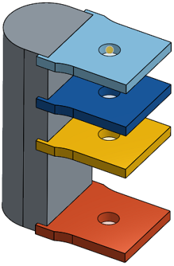
홀 계산은 홀 피처의 병합 범위를 기반으로 여러 금속 판재 파트에 영향을 줄 수 있습니다. 아래 예에서는 접촉하는 플랜지가 있는 2개의 판금 파트가 생성됩니다. 카운터싱크 홀이 모델에 추가되고 두 파트가 모두 홀의 병합 범위에 포함되면 결과적으로 두 파트를 관통하는 카운터싱크 홀이 생성됩니다.
단방향
선택한 파트에서 지정된 깊이까지.
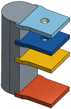
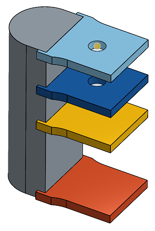
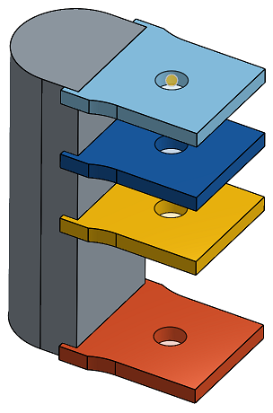
단방향이 종료 조건으로 선택되고 깊이가 10인치로 설정된 상태의 단순 홀로, 상단의 2개 플레이트만을 통과합니다.
다음까지
지정된 방향으로 발생한 다음 면(들)까지.
종료 조건으로 다음까지를 선택한 단순 홀:
선택 요소까지
지정된 방향으로 발생한 다음(선택한) 요소까지.
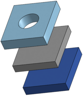
선택 요소까지를 종료 조건으로 선택하고 짙은 파란색 파트를 선택한 요소로 선택한 상태의 단순 홀:
전체 범위
선택한 파트(들)를 완전히 통과합니다.
'통과'가 종료 조건으로 설정되고 4개 플레이트 모두를 선택한 상태의 단순 홀:
다음까지 또는 요소까지 끝 조건을 사용할 경우, 테이퍼 깊이 입력이 계산된 최소 홀 깊이보다 크면 테이퍼 깊이가 재조정되고 다음의 메시지가 표시됩니다.

-
계산된 홀 깊이가 입력된 테이퍼 깊이보다 크면 테이퍼 깊이가 재조정되지 않습니다.
-
계산된 홀 깊이가 입력된 테이퍼 깊이보다 작으면 테이퍼 깊이 값이 계산된 홀 깊이 값으로 조정됩니다.
관통하는 홀의 경우, 계산된 홀 깊이와 테이퍼 깊이 값 모두가 도면의 홀/나사산 설명서에 THRU를 표시합니다.
- 스케치 면의 점과 홀 사이의 모든 재질이 삭제됩니다.
- 스케치를 변경하면 홀 피처가 다시 계산됩니다.
- 이 피처에는 홀에 대해 올바른 시작 깊이를 결정하기 위한 논리가 포함되며, 곡면 또는 불규칙한 면의 경우 유용합니다. 이 피처는 기본 설정입니다. 홀 시작을 스케치 면에서 찾으려면 이 상자를 체크하십시오(시작 깊이 논리를 효과적으로 끕니다). 이 상자를 체크하면 중첩되는 홀을 생성할 수도 있습니다.
- 홀 피처의 충돌 또는 중첩이 발생하거나 홀이 목표 파트에 완전히 놓이지 않은 경우, 스케치 면에서 0 깊이로 홀이 뚫립니다.
-
표준이 카운터보어, 카운터싱크 또는 탭 지름을 제공하지 않는 경우, 이들 값이 범위를 벗어나면 값이 재설정됩니다.
-
파트를 두 개 이상 선택하고 데이퍼 > 패스너 맞춤을없음 이외의 값으로 설정하면, 초기 홀은 여유 값 홀이고 마지막 홀은 테이퍼입니다(이 방법은 더 이상 사용되지 않는 마지막 단방향 옵션을 대체합니다).
스케치 점, 원 중심 및 메이트 커넥터에 간단한 카운터싱크 구멍, 카운터보어 구멍을 만들 수 있습니다.
- 홀 도구()를 탭합니다.
-
측정값 (인치 또는 미터) 을 선택합니다.
- 홀 스타일을 선택합니다.
- Simple - A uniform-diameter drilled hole.
- Counterbore - A cylindrical flat-bottomed drilled hole that enlarges another coaxial drilled hole.
- Countersink - A drilled hole with a conical relief at the top.
- 스케치에서 구멍 중심을 배치할 점 (형상의 모서리, 선 끝, 스플라인 점, 원 중심 등 포함) 을 선택합니다.
- 메이트 커넥터 아이콘()을 눌러 암시적 메이트 커넥터를 스케치 점 대신 점으로 선택하거나 만들 수 있습니다.
- 메이트 커넥터 아이콘(
- 병합 스코프를눌러 구멍을 포함할 파트를 선택합니다.
- 구멍 유형을 누르고 구멍 유형을 선택한 다음 필요에 맞는 사양을 선택합니다.모든 구멍 유형에 모든 구멍 유형 사양을 사용할 수 있는 것은 아닙니다.
- Drilled - Creates a drilled hole.
- Drill size - Select a Drill size from the dropdown list.
- Clearance - Creates a clearance hole.
- Size - Select a Clearance size from the dropdown list.
- Fastener fit - Select from Close, Free, Close (ASME), Normal (ASME), Loose (ASME)
- Tapped - Creates a tapped hole.
- Tap type - Select either Straight tap or Tapered pipe tap.
- Size - Select a tapped hole size from the dropdown list.
- Threads/inch - Select the number of threads per inch (tpi) setting from the dropdown list.
- Class - Depends on size selection. Select from 1B, 2B, or 3B.
- Fastener fit - Available only for Straight tap Tap type when 2 or more parts are selected in the Merge scope field. Select from None, Close, Free, Close (ASME), Normal (ASME), Loose (ASME).
- PEM® - PennEngineering® fasteners. This option is not available for counterbored or countersunk holes.
- Fastener - Select from Self-clinching nuts, Self-clinching standoffs, Self-clinghing studs & pins
- Fastener type - Select from S™/SS™/CLS™/CLSS™/SP™ nuts, CLA™ free running locknuts, S-RT™ Free-running locknuts, SL™ TRI-DENT® Prevailing torque locknuts, Self-clinching nuts, H™ Nuts/HNL™ Prevailing torque locknuts, SH™ Hard panel nuts, SMPS™/SMPP™ Nuts.
- Size - Select a tapped hole size from the dropdown list.
- Fastener fit - Clearance.
- Drilled - Creates a drilled hole.
- 구멍의 지름 공차 컨트롤을 입력합니다.
- Diameter - Enter a diameter value for the hole.
- Precision - Select a precision for the hole, either Workspace precision or another precision value from the dropdown list.
- Tolerance type - Select a tolerance type for the hole from the dropdown list. Options are No tolerance, Symmetrical, Deviation, Limits, Min, Max, Fit, Fit with tolerance, Fit (tolerance only).
- Deviation - Available for the Symmetrical Tolerance type. Enter a deviation value.
- Upper - Available for the Deviation, Limits, Fit tolerance, Fit with tolerance, and Fit (tolerance only) Tolerance types. Tolerance type. Enter the upper tolerance value.
- Lower -Deviation, Limits, Fit tolerance, Fit with tolerance, and Fit (tolerance only) Tolerance types. Enter the lower tolerance value.
- Standard - Available for the Fit Tolerance type. Select the ANSI or ISO standard from the dropdown list.
- Fit type - Available for the Fit Tolerance type. Select User defined, Clearance, Transition, or Interference from the dropdown list.
- Hole class - Available for the Fit tolerance, Fit with tolerance, and Fit (tolerance only) Tolerance types. Select H5, H6, H7, H8, H9, H10, H11 from the dropdown list.
- Shaft class - Available for the Fit tolerance, Fit with tolerance, and Fit (tolerance only) Tolerance types when the ISO Standard is selected. Select a Shaft class from the dropdown list.
- 구멍의 시작 평면을 선택합니다.
- Start from part - the hole begins from the part face.
- Start from sketch plane - The hole begins from the sketch plane.
- Start from selected plane - The hole begins from a selected plane.
- Hole start plane or mate connector - Select the entity (plane or mate connector) from which the hole begins.
이 옵션을 사용하면 홀이 서로 다른 높이에서 시작될 때 파트의 동일한 위치에서 깊이 끝을 제어할 수 있습니다.예를 들어, 홀의 모든 스케치 점이 한 평면에 있습니다.
깊이가 1인치인 카운터보어 홀의 경우, 홀이 스케치 면에서 시작하지 않을 때 더 짧은 홀에는 카운터보어만 포함되고, 가장 깊은 홀에는 카운터보어와 볼트 샤프트가 포함됩니다.
그러나 홀이 스케치 면에서 시작하는 경우, 먼저 샤프트가 배치되고 카운터보어가 단축됩니다.
동일한 시나리오가 카운터싱크 홀에도 적용됩니다. 단순 홀은 깊이에 대해서만 조정됩니다.
- 해지 (종료) 조건을 선택합니다.모든 종료 종료 조건의 경우 반대 방향 토글을 눌러 구멍 방향을 전환합니다.
- Blind - The hole ends at a specified depth in the selected part.
- Depth - Enter the depth value for the hole, inclusive of the counterbore or countersink depth.
- Precision - Select a precision for the hole depth, either Workspace precision or another precision value from the dropdown list.
- Tolerance type - Select a tolerance type for the hole from the dropdown list. Options are No tolerance, Symmetrical, Deviation, Limits, Min, and Max.
- Deviation - Available for the Symmetrical Tolerance type. Enter a deviation value.
- Upper - Available for the Deviation, Limits, Fit tolerance, Fit with tolerance, and Fit (tolerance only) Tolerance types. Tolerance type. Enter the upper tolerance value.
- Lower -Deviation, Limits, Fit tolerance, Fit with tolerance, and Fit (tolerance only) Tolerance types. Enter the lower tolerance value.
- Counterbore diameter - For counterbore holes, enter the diameter value for the hole tip, as well as Precision and Tolerance controls, which are the same as those found above, under Blind > Depth.
- Counterbore depth - For counterbore holes, enter the depth value of the enlarged hole, as well as Precision and Tolerance controls, which are the same as those found above, under Blind > Depth.
- Countersink diameter - For countersink holes, enter the diameter value of the enlarged hole, as well as Precision and Tolerance controls, which are the same as those found above, under Blind > Depth.
- Countersink angle - For countersink holes, enter the angle value of the hole, as well as Precision and Tolerance controls, which are the same as those found above, under Blind > Depth.
- Tapped depth - For tapped holes, the full thread depth of a tapped hole, in document units (or specify other units). Precision and Tolerance type controls have the same options as listed above, under the Depth tolerance controls.
- Tap clearance - For blind tapped holes, the number of thread pitch lengths between the bottom of the Tapped depth and bottom of the hole.
한계 또는 편차 공차 유형을 선택한 겨우, 하한 및 상한 경계에 대해 제로(0)와 음수 값이 허용됩니다. 계산된 하한 경계가 계산된 상한 경계보다 클 경우 오류가 발생합니다. 계산된 상한 및 하한 경계가 같을 수 있습니다.
- Depth - Enter the depth value for the hole, inclusive of the counterbore or countersink depth.
- Up to next - Up to the next face or faces encountered.
- Offset from tip - Tap the toggle to enter an offset distance value from the hole tip. Tap the Opposite direction toggle to flip the offset.
- Depth - Multiple.
- Precision and Tolerance type controls - Same options as those found above, under Blind > Depth.
- Up to entity - Up to a selected entity or Mate connector.
- Up to entity or mate connector - Select the entity (for example, a face or plane) or Mate connector ().
- Offset from tip - Tap the toggle to enter an offset distance value from the hole tip. Tap the Opposite direction toggle to flip the offset.
- Depth - Multiple.
- Precision and Tolerance type controls - Same options as those found above, under Blind > Depth.
- Up to entity or mate connector - Select the entity (for example, a face or plane) or Mate connector (
- Through all - Completely through the part(s) selected in the Merge scope.
- Tap through all - For tapped holes, Keep the toggle on to create thread for the full length of the hole. Tap the toggle off to specify:
- Tapped depth - Enter a custom thread depth.
- Precision and Tolerance type controls - Same options as those found above, under Blind > Depth.
- Tap through all - For tapped holes, Keep the toggle on to create thread for the full length of the hole. Tap the toggle off to specify:
- Blind - The hole ends at a specified depth in the selected part.
- 구멍의 팁 각도 스타일을 선택합니다.옵션은 118도, 135도, 플랫 또는 사용자 지정으로 사용자 지정할 수 있습니다.
- Tip angle - For custom holes, enter a Tip angle value.
- Precision and Tolerance type controls - Same options as those found above, under Blind > Depth.
- 체크마크를 눌러 구멍을 생성합니다.
일정 지름의 드릴 홀
단방향
선택한 파트에서 지정된 깊이까지.
이것은 단방향이 종료 조건으로 선택되고 깊이가 10인치로 설정된 상태의 단순 홀을 보여줍니다. 따라서, 홀은 플레이트를 통과해 10인치로 생성되며, 상단의 2개 플레이트만을 통과합니다.
다음까지
지정된 방향으로 발생한 다음 면(들)까지.
종료 조건으로 다음까지를 선택한 단순 홀:
선택 요소까지
지정된 방향으로 발생한 다음(선택한) 요소까지.
선택 요소까지를 종료 조건으로 선택하고 짙은 파란색 파트를 선택한 요소로 선택한 상태의 단순 홀:
전체 범위
선택한 파트(들)를 완전히 통과합니다.
이것은 통과가 종료 조건으로 설정되고 4개 플레이트 모두를 선택한 상태의 단순홀을 보여줍니다. 따라서, 홀은 4개 파트를 모두 통과합니다.
- 스케치 면의 점과 홀 사이의 모든 재질이 삭제됩니다.
- 스케치를 변경하면 홀 피처가 다시 계산됩니다.
- 이 기능에는 홀의 적절한 시작 깊이를 결정하는 로직이 포함되어 있어 곡면이나 불규칙한 표면에 유용합니다. 이것이 기본값입니다. 홀 시작 부분이 스케치 평면에 위치하도록 하려면 스케치 평면에서 시작을 토글하십시오(시작 뎁스 로직을 효과적으로 끕니다). 이 옵션을 켜면 겹치는 홀을 만들 수도 있습니다.
- 홀 피처의 충돌 또는 중첩이 발생하거나 홀이 목표 파트에 완전히 놓이지 않은 경우, 스케치 면에서 0 깊이로 홀이 뚫립니다.
- 표준이 카운터보어, 카운터싱크 또는 탭 지름을 제공하지 않는 경우, 이들 값이 범위를 벗어나면 값이 재설정됩니다.
- 파트를 두 개 이상 선택하고 데이퍼 > 패스너 맞춤을없음 이외의 값으로 설정하면, 초기 홀은 여유 값 홀이고 마지막 홀은 테이퍼입니다(이 방법은 더 이상 사용되지 않는 마지막 단방향 옵션을 대체합니다).
스케치 점, 원 중심 및 메이트 커넥터에 간단한 카운터싱크 구멍, 카운터보어 구멍을 만들 수 있습니다.
- 홀 도구()를 탭합니다.
-
측정 단위 (인치 또는 미터) 를 선택합니다.
- 홀 스타일을 선택합니다.
- Simple - A uniform-diameter drilled hole.
- Counterbore - A cylindrical flat-bottomed drilled hole that enlarges another coaxial drilled hole.
- Countersink - A drilled hole with a conical relief at the top.
- 스케치에서 구멍 중심을 배치할 점 (형상의 모서리, 선 끝, 스플라인 점, 원 중심 등 포함) 을 선택합니다.
- 메이트 커넥터 아이콘()을 눌러 암시적 메이트 커넥터를 스케치 점 대신 점으로 선택하거나 만들 수 있습니다.
- 메이트 커넥터 아이콘(
- 병합 스코프를눌러 구멍을 포함할 파트를 선택합니다.
- 구멍 유형을 누르고 구멍 유형을 선택한 다음 필요에 맞는 사양을 선택합니다.모든 구멍 유형에 모든 구멍 유형 사양을 사용할 수 있는 것은 아닙니다.
- Drilled - Creates a drilled hole.
- Drill size - Select a Drill size from the dropdown list.
- Clearance - Creates a clearance hole.
- Size - Select a Clearance size from the dropdown list.
- Fastener fit - Select from Close, Free, Close (ASME), Normal (ASME), Loose (ASME)
- Tapped - Creates a tapped hole.
- Tap type - Select either Straight tap or Tapered pipe tap.
- Size - Select a tapped hole size from the dropdown list.
- Threads/inch - Select the number of threads per inch (tpi) setting from the dropdown list.
- Class - Depends on size selection. Select from 1B, 2B, or 3B.
- Fastener fit - Available only for Straight tap Tap type when 2 or more parts are selected in the Merge scope field. Select from None, Close, Free, Close (ASME), Normal (ASME), Loose (ASME).
- PEM® - PennEngineering® fasteners. This option is not available for counterbored or countersunk holes.
- Fastener - Select from Self-clinching nuts, Self-clinching standoffs, Self-clinghing studs & pins
- Fastener type - Select from S™/SS™/CLS™/CLSS™/SP™ nuts, CLA™ free running locknuts, S-RT™ Free-running locknuts, SL™ TRI-DENT® Prevailing torque locknuts, Self-clinching nuts, H™ Nuts/HNL™ Prevailing torque locknuts, SH™ Hard panel nuts, SMPS™/SMPP™ Nuts.
- Size - Select a tapped hole size from the dropdown list.
- Fastener fit - Clearance.
- Drilled - Creates a drilled hole.
- 구멍의 지름 공차 컨트롤을 입력합니다.
- Diameter - Enter a diameter value for the hole.
- Precision - Select a precision for the hole, either Workspace precision or another precision value from the dropdown list.
- Tolerance type - Select a tolerance type for the hole from the dropdown list. Options are No tolerance, Symmetrical, Deviation, Limits, Min, Max, Fit, Fit with tolerance, Fit (tolerance only).
- Deviation - Available for the Symmetrical Tolerance type. Enter a deviation value.
- Upper - Available for the Deviation, Limits, Fit tolerance, Fit with tolerance, and Fit (tolerance only) Tolerance types. Tolerance type. Enter the upper tolerance value.
- Lower -Deviation, Limits, Fit tolerance, Fit with tolerance, and Fit (tolerance only) Tolerance types. Enter the lower tolerance value.
- Standard - Available for the Fit Tolerance type. Select the ANSI or ISO standard from the dropdown list.
- Fit type - Available for the Fit Tolerance type. Select User defined, Clearance, Transition, or Interference from the dropdown list.
- Hole class - Available for the Fit tolerance, Fit with tolerance, and Fit (tolerance only) Tolerance types. Select H5, H6, H7, H8, H9, H10, H11 from the dropdown list.
- Shaft class - Available for the Fit tolerance, Fit with tolerance, and Fit (tolerance only) Tolerance types when the ISO Standard is selected. Select a Shaft class from the dropdown list.
- 구멍의 시작 평면을 선택합니다.
- Start from part - the hole begins from the part face.
- Start from sketch plane - The hole begins from the sketch plane.
- Start from selected plane - The hole begins from a selected plane.
- Hole start plane or mate connector - Select the entity (plane or mate connector) from which the hole begins.
이 옵션을 사용하면 홀이 서로 다른 높이에서 시작될 때 파트의 동일한 위치에서 깊이 끝을 제어할 수 있습니다.예를 들어, 홀의 모든 스케치 점이 한 평면에 있습니다.
깊이가 1인치인 카운터보어 홀의 경우, 홀이 스케치 면에서 시작하지 않을 때 더 짧은 홀에는 카운터보어만 포함되고, 가장 깊은 홀에는 카운터보어와 볼트 샤프트가 포함됩니다.
그러나 홀이 스케치 면에서 시작하는 경우, 먼저 샤프트가 배치되고 카운터보어가 단축됩니다.
동일한 시나리오가 카운터싱크 홀에도 적용됩니다. 단순 홀은 깊이에 대해서만 조정됩니다.
- 해지 (종료) 조건을 선택합니다.모든 종료 종료 조건의 경우 반대 방향 토글을 눌러 구멍 방향을 전환합니다.
- Blind - The hole ends at a specified depth in the selected part.
- Depth - Enter the depth value for the hole, inclusive of the counterbore or countersink depth.
- Precision - Select a precision for the hole depth, either Workspace precision or another precision value from the dropdown list.
- Tolerance type - Select a tolerance type for the hole from the dropdown list. Options are No tolerance, Symmetrical, Deviation, Limits, Min, and Max.
- Deviation - Available for the Symmetrical Tolerance type. Enter a deviation value.
- Upper - Available for the Deviation, Limits, Fit tolerance, Fit with tolerance, and Fit (tolerance only) Tolerance types. Tolerance type. Enter the upper tolerance value.
- Lower -Deviation, Limits, Fit tolerance, Fit with tolerance, and Fit (tolerance only) Tolerance types. Enter the lower tolerance value.
- Counterbore diameter - For counterbore holes, enter the diameter value for the hole tip, as well as Precision and Tolerance controls, which are the same as those found above, under Blind > Depth.
- Counterbore depth - For counterbore holes, enter the depth value of the enlarged hole, as well as Precision and Tolerance controls, which are the same as those found above, under Blind > Depth.
- Countersink diameter - For countersink holes, enter the diameter value of the enlarged hole, as well as Precision and Tolerance controls, which are the same as those found above, under Blind > Depth.
- Countersink angle - For countersink holes, enter the angle value of the hole, as well as Precision and Tolerance controls, which are the same as those found above, under Blind > Depth.
- Tapped depth - For tapped holes, the full thread depth of a tapped hole, in document units (or specify other units). Precision and Tolerance type controls have the same options as listed above, under the Depth tolerance controls.
- Tap clearance - For blind tapped holes, the number of thread pitch lengths between the bottom of the Tapped depth and bottom of the hole.
한계 또는 편차 공차 유형을 선택한 겨우, 하한 및 상한 경계에 대해 제로(0)와 음수 값이 허용됩니다. 계산된 하한 경계가 계산된 상한 경계보다 클 경우 오류가 발생합니다. 계산된 상한 및 하한 경계가 같을 수 있습니다.
- Depth - Enter the depth value for the hole, inclusive of the counterbore or countersink depth.
- Up to next - Up to the next face or faces encountered.
- Offset from tip - Tap the toggle to enter an offset distance value from the hole tip. Tap the Opposite direction toggle to flip the offset.
- Depth - Multiple.
- Precision and Tolerance type controls - Same options as those found above, under Blind > Depth.
- Up to entity - Up to a selected entity or Mate connector.
- Up to entity or mate connector - Select the entity (for example, a face or plane) or Mate connector ().
- Offset from tip - Tap the toggle to enter an offset distance value from the hole tip. Tap the Opposite direction toggle to flip the offset.
- Depth - Multiple.
- Precision and Tolerance type controls - Same options as those found above, under Blind > Depth.
- Up to entity or mate connector - Select the entity (for example, a face or plane) or Mate connector (
- Through all - Completely through the part(s) selected in the Merge scope.
- Tap through all - For tapped holes, Keep the toggle on to create thread for the full length of the hole. Tap the toggle off to specify:
- Tapped depth - Enter a custom thread depth.
- Precision and Tolerance type controls - Same options as those found above, under Blind > Depth.
- Tap through all - For tapped holes, Keep the toggle on to create thread for the full length of the hole. Tap the toggle off to specify:
- Blind - The hole ends at a specified depth in the selected part.
- 구멍의 팁 각도 스타일을 선택합니다.옵션은 118도, 135도, 플랫 또는 사용자 지정으로 사용자 지정할 수 있습니다.
- Tip angle - For custom holes, enter a Tip angle value.
- Precision and Tolerance type controls - Same options as those found above, under Blind > Depth.
- 체크마크를 탭합니다.
일정 지름의 드릴 홀
단방향
선택한 파트에서 지정된 깊이까지.
이것은 단방향이 종료 조건으로 선택되고 깊이가 10인치로 설정된 상태의 단순 홀을 보여줍니다. 따라서, 홀은 플레이트를 통과해 10인치로 생성되며, 상단의 2개 플레이트만을 통과합니다.
다음까지
지정된 방향으로 발생한 다음 면(들)까지.
종료 조건으로 다음까지를 선택한 단순 홀:
선택 요소까지
지정된 방향으로 발생한 다음(선택한) 요소까지.
선택 요소까지를 종료 조건으로 선택하고 짙은 파란색 파트를 선택한 요소로 선택한 상태의 단순 홀:
전체 범위
선택한 파트(들)를 완전히 통과합니다.
이것은 통과가 종료 조건으로 설정되고 4개 플레이트 모두를 선택한 상태의 단순홀을 보여줍니다. 따라서, 홀은 4개 파트를 모두 통과합니다.
- 스케치 면의 점과 홀 사이의 모든 재질이 삭제됩니다.
- 스케치를 변경하면 홀 피처가 다시 계산됩니다.
- 이 기능에는 홀의 적절한 시작 깊이를 결정하는 로직이 포함되어 있어 곡면이나 불규칙한 표면에 유용합니다. 이것이 기본값입니다. 홀 시작 부분이 스케치 평면에 위치하도록 하려면 스케치 평면에서 시작을 토글하십시오(시작 뎁스 로직을 효과적으로 끕니다). 이 옵션을 켜면 겹치는 홀을 만들 수도 있습니다.
- 홀 피처의 충돌 또는 중첩이 발생하거나 홀이 목표 파트에 완전히 놓이지 않은 경우, 스케치 면에서 0 깊이로 홀이 뚫립니다.
- 표준이 카운터보어, 카운터싱크 또는 탭 지름을 제공하지 않는 경우, 이들 값이 범위를 벗어나면 값이 재설정됩니다.
- 파트를 두 개 이상 선택하고 데이퍼 > 패스너 맞춤을없음 이외의 값으로 설정하면, 초기 홀은 여유 값 홀이고 마지막 홀은 테이퍼입니다(이 방법은 더 이상 사용되지 않는 마지막 단방향 옵션을 대체합니다).