구속 조건 사용하기
![]()
![]()
![]()
구속 조건은 스케치를 생성할 때에만 사용할 수 있고 보기가 가능하며, 그 밖의 경우에는 편집이 가능합니다.
두 스케치에서 요소들 간에 적용되는 구속 조건(예를 들어, 한 스케치의 요소를 다른 스케치에서 사용할 때)은 파란색 배경으로 구분됩니다. 구속 조건을 수동으로 적용할 수 있으며, 일부는 스케치로 형상이 생성될 때 만들어집니다. 마우스로 가리킬 때, 참조된 구속 조건의 배경은 더 짙은 파란색이 됩니다.
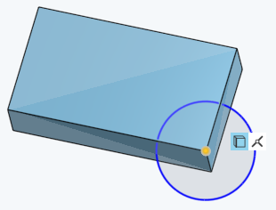
위에 표시된 사용 구속 조건(파란색 배경)은 직사각형 스케치의 꼭지점을 원 스케치에서 원의 중심점으로 구속합니다.
구속 조건 스케치 도구를 이용하면 스케치를 작성 중이거나 편집을 위해 열었을 때 구속 조건을 보고 변경할 수 있습니다. 두 스케치에서 요소들 간에 적용되는 구속 조건(예를 들어, 한 스케치의 요소를 다른 스케치에서 사용할 때)은 파란색 배경으로 구분됩니다. 구속 조건을 수동으로 적용할 수 있으며, 일부는 스케치로 형상이 생성될 때 만들어집니다. 마우스로 가리킬 때, 참조된 구속 조건의 배경은 더 짙은 파란색이 됩니다.
일치, 동심, 평행, 접선, 수평,수직, 직교, 같음, 중심점, 수직, 관통, 대칭, 고정, 곡률 등 여러 가지 구속 조건을 사용할 수 있습니다. 구속 조건은 구속 제한을 사용해 자동으로, 툴바를 사용해 수동으로 스케치에 추가될 수 있습니다.
이 예에서는 수직 보조선과 원 사이에 중심점 구속이 추가됩니다. 원과 보조선의 중심점을 선택합니다. 스케치 툴바에서 중심점 구속 조건을 클릭합니다. 다른 구속 조건에 대해서 이 프로세스를 모방할 수 있습니다. 또는 먼저 스케치 툴바에서 중심점 구속 조건을 선택한 다음, 보조선과 원을 선택합니다.
도면 구속 조건을 적용하려면 다음 중 하나를 수행하십시오.
-
메뉴에서 구속 조건을 선택하거나 해당 바로가기 키를 사용하여 스케치에서 구속 조건을 적용할 요소를 선택합니다.
-
스케치 요소를 선택하고 도구 모음의 구속 조건 메뉴에서 구속 조건을 클릭합니다.
툴바 제약 조건 메뉴에서 사용할 수 있는 구속 조건은 다음과 같습니다.
-
일치 - 두 개 이상의 스케치 요소가 스케치에서 같은 위치를 공유하도록 합니다.
-
동심원 - 임의의 점을 호 또는 원의 중심과 일치시키십시오. 선택한 호와 원이 중심점을 공유하도록 합니다.
-
평행 - 2개 이상의 선을 평행하게 만듭니다.
-
접선 - 두 스케치 요소 사이 또는 스케치 요소와 평면 사이의 접선 관계를 만듭니다.
-
가로 - 하나 이상의 선 또는 점 집합을 가로로 제한합니다.
-
수직 - 하나 이상의 선 또는 점 집합을 수직으로 제한합니다.
-
직교 - 두 선을 직교하도록 만듭니다.
-
같음 - 여러 줄의 길이를 같게 하거나 여러 호의 반지름을 같게 만듭니다.
-
중심점 - 스케치 점을 선 또는 호의 중심점으로 제한합니다.
-
직교 - 곡선과 선 또는 곡선과 면을 수직으로 만듭니다.
-
관통 - 스케치 요소를 활성 스케치 평면 외부의 다른 요소와 일치하게 만듭니다.
-
대칭 - 동일한 유형의 두 엔티티를 선, 면 또는 선형 모서리를 기준으로 대칭으로 만듭니다.
-
고정 - 움직이지 않도록 스케치 요소를 스케치 평면에 잠급니다.
-
곡률 - 스케치 스플라인(또는 원추형) 및 주변 형상 간에 곡률 연속 전환을 생성합니다.
스케치를 연 상태에서, 선이나 호와 같은 스케치 요소 위에 마우스를 올려놓으면 해당 요소에 대한 구속 조건을 볼 수 있습니다. 마우스를 움직여 요소 위에 올려놓으면 강조 표시된 요소에 대해서만 구속 조건이 나타납니다. 모든 구속 조건이 표시되게 하려면 Shift 키를 누른 상태에서 마우스를 움직이십시오.
마우스를 위에 올려놓으면 요소는 오렌지색으로 강조표시됩니다. 파란색 바탕의 참조된 구속 조건은 예외이며, 마우스를 올려놓으면 더 어두운 파란색으로 강조표시됩니다.관련 요소는 노란색으로 강조표시되며, 구속 조건을 선택하면 좌표 요소도 강조표시됩니다.
이러한 구속 조건은 툴바의 구속 조건 섹션에서 사용할 수 없지만, 아래의 설명과 같이 특정 작업 동안 자동으로 생성됩니다.
-
 사분면 - 타원과 일치하는 점과 해당 타원의 장축 또는 단축 중 하나를 구속합니다. 특정 요소를 드래그하거나 타원상의 점들 중 하나에 배치하는 등 구속 제한에 의해 형성될 수 있습니다.
 -
 사용 - 한 스케치의 스케치 요소를 다른 스케치의 요소로 구속합니다. 사용 도구를 선택한 다음, 다른 스케치 또는 피처에서 요소(스케치 요소, 면, 모서리)를 선택하여 수행됩니다.
 -
 교차점 - 관통 구속 조건
  을 사용하여 열린 곡선의 끝점이 교차면의 모서리에 놓이도록 구속합니다(교차점 도구를 사용한 결과). 닫힌 곡선의 경우, 교차점 구속 조건을 사용하여 스케치 요소를 구속합니다.
스케치 요소의 색상은 구속 상태를 나타냅니다.
- 파란색은 구속 조건이 적용 중임을 의미합니다.
- 검정색은 완전히 구속됨을 의미합니다.
- 빨간색은 구속 조건 문제를 나타냅니다(과도한 구속).
구속 조건 아이콘의 색상은 구속 상태를 나타냅니다.
- 회색 바탕의 검은색은 잘 정의되어 있음을 의미합니다.
- 빨간색 바탕의 흰색은 문제를 나타냅니다.
- 선택 시 완전히 구속되지 않은 스케치 점(파란색 및 빨간색)이 완전히 구속된 중첩된 스케치 점(검은색)보다 우선 순위가 지정됩니다.
치수 또는 구속 조건을 더 추가하면 스케치가 추가로 구속됩니다. 요소를 드래그해서 추가하려는 구속 조건 또는 치수가 어떻게 적용되는지를 쉽게 이해할 수 있습니다.
스케치 구속 조건과 치수를 확인하고 필터링하여 이를 분석하고 스케치 구속 조건 오류를 수정합니다.
구속 조건 관리자 액세스
스케치 대화상자에서:
-
스케치 진단 도구 표시 아이콘(
 )을 클릭합니다.
 -
구속 조건 관리자를 클릭합니다.
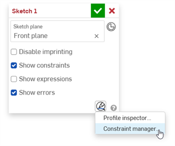
구속 조건 관리자 대화상자가 열립니다.
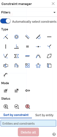
구속 조건 관리자 사용
구속 조건 관리자 대화상자에서는 다음 작업을 수행할 수 있습니다.
-
필터 - 모든 대화상자 섹션을 한 번에 축소/확장합니다(유형, 모드, 상태).
-
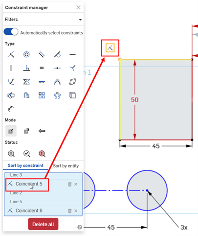
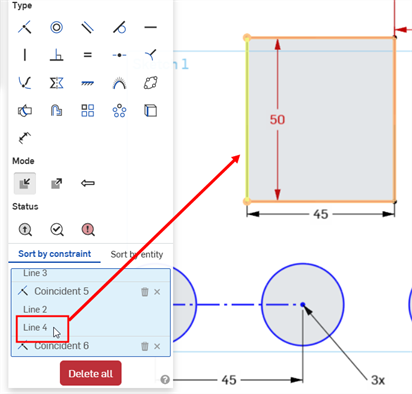
구속 조건 자동 선택 - 이 옵션을 켜짐(기본값)으로 설정하면, 구속 조건 관리자 대화상자에서 선택한 모든 구속 조건이 스케치의 해당 구속 조건 주위에 노란색 경계 상자를 표시합니다. 끄면 구속 조건 주위에 경계 상자가 표시되지 않습니다(구속 조건이 선택되지 않음).
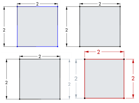
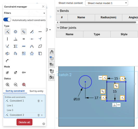
이 옵션은 스케치의 특정 부분에서 해당 구속 조건만 선택하려는 경우에 유용합니다. 예를 들어, 이 옵션을 끕니다. 스케치 부분에서 찾으려는 구속 조건 유형을 선택합니다(예: 아래 예의 일치 구속 조건). 그런 다음 스케치의 일부(아래 예의 직사각형) 주위에 선택 상자를 만듭니다. 해당 섹션의 구속 조건만 해당 섹션 주위에 경계 상자를 표시하며 요소 및 구속 조건 목록에서 사용할 수 있습니다(아래 참조).
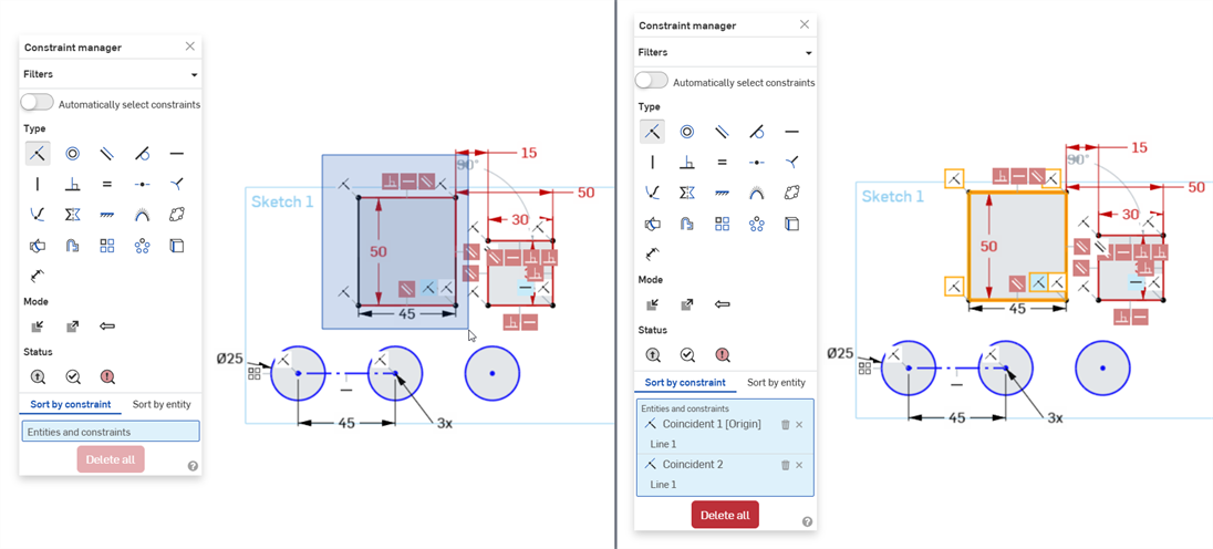
"구속 조건 자동 선택"을 비활성화한 후 스케치에서 직사각형에 해당하는 상자를 선택합니다(왼쪽). 선택하면 필터는 선택한 스케치 요소에만 적용됩니다. 이 예시에서는 일치 구속 조건이 이전에 선택한 직사각형에만 표시됩니다(오른쪽).
-
유형 - 사용 가능한 구속 조건 목록에서 선택합니다. 예를 들어, 일치를 선택하면 스케치에서 모든 일치 구속 조건 주위에 노란색 경계 상자가 표시됩니다("구속 조건 자동 선택"이 활성화된 경우).
-
모드 - 다음 3가지 모드 중 하나를 선택합니다.
-
내부 - 현재 스케치에서 구속 조건을 선택합니다.
-
외부 - 외부 소스에서 구속 조건을 선택합니다.
-
컨텍스트 내 - 컨텍스트 내에서 참조되는 구속 조건을 선택합니다.
-
-
상태 - 다음 세 가지 상태 중에서 선택합니다.
-
구동 - 구동 구속 조건입니다. 선택하면 구동 구속 조건이 노란색으로 강조 표시됩니다. 구속 조건이 부족하면 더 진한 파란색으로 강조 표시됩니다.
-
해결됨 - 해결된 구속 조건입니다. 이 옵션을 선택하면 해결된 구속 조건이 노란색으로 강조 표시됩니다. 구속 조건이 부족한 경우 더 진한 파란색으로 강조 표시됩니다.
-
오류 - 오류가 있는 구속 조건입니다. 이 옵션을 선택하면 오류가 있는 구속 조건이 진한 빨간색으로 강조 표시됩니다.
-
-
구속 조건별 정렬 - 아래의 요소 및 구속 조건 목록을 먼저 구속 조건별로 정렬한 다음, 두 번째로 요소별로 정렬합니다.
-
요소별 정렬 - 아래의 요소 및 구속 조건 목록을 먼저 요소별로 정렬한 다음 구속 조건별로 정렬합니다.
-
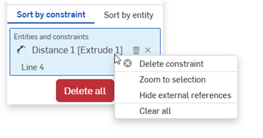
요소 및 구속 조건 목록 - 대화상자의 필터 선택에 따라 선택한 모든 구속 조건을 표시합니다. 목록의 구속 조건이나 요소 위에 커서를 놓으면 스케치에서 해당 요소나 요소가 강조 표시됩니다. 이 목록에서 다음을 수행할 수 있습니다.
-
구속 조건 삭제(
 ) - 스케치에서 구속 조건을 삭제합니다.
 -
선택 항목 제거(
 ) - 요소 및 구속 조건 목록에서 구속 조건을 제거합니다.
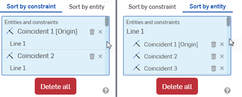
구속 조건별 정렬(왼쪽), 요소별 정렬(오른쪽)
요소 및 구속 조건 목록에서 구속 조건이나 요소를 마우스 오른쪽 버튼으로 클릭하면 다음 명령에 액세스할 수 있습니다.
-
구속 조건/요소 삭제 - 선택 항목(구속 조건 또는 요소)을 삭제합니다.
-
선택 항목 확대/축소 - 선택 항목(구속 조건 또는 요소)을 확대/축소합니다.
-
외부 참조 숨기기 - 모든 외부 참조 구속 조건을 숨깁니다.
-
모두 지우기 - 요소 및 구속 조건 목록에서 모든 구속 조건을 지웁니다.
-
-
-
모두 삭제 - 스케치에서 선택한 모든 구속 조건을 삭제합니다.
구속 조건 관리자 끄기(Turning Constraint manager off)
구속 조건 관리자를 끄려면 다음 중 하나를 수행하십시오.
-
구속 조건 관리자 대화상자의 오른쪽 위 코너에 있는 X를 클릭합니다.
-
스케치 진단 도구 표시 아이콘(
)을 클릭하고 구속 조건 관리자 끄기를 선택합니다.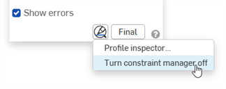
팁
-
대화상자에서 유형, 모드 및 상태를 원하는 만큼 선택하여 선택한 항목으로 구속 조건을 필터링합니다. 이러한 필터는 어떤 조합으로도 사용할 수 있습니다.
-
스케치 대화 상자에서 구속 조건 표시 및 오류 표시가 비활성화된 경우, 요소 및 구속 조건 목록에서 구속 조건 위에 마우스를 올려 놓으면 스케치에서 해당 구속 조건(및 관련 요소)만 표시됩니다.
-
요소 및 구속 조건 목록에서 요소를 선택하면 해당 요소가 밝은 노란색으로 강조 표시됩니다.
-
구속 조건 관리자는 금속 판재 플랫 패턴 뷰의 스케치에서도 작동합니다.
구속 조건 아이콘과 상호 작용할 수 있습니다.
- 아이콘 또는 아이콘 그룹을 클릭해서 다른 위치로 드래그합니다.
- 단일 구속 조건 아이콘 위로 마우스를 가져가면 어떤 요소가 강조 표시되는지 확인할 수 있으며, 해당 요소에 구속 조건이 적용됨을 나타냅니다.
- 구속 조건 삭제: 단일 구속 조건 아이콘을 클릭하고 삭제를 클릭하거나 컨텍스트 메뉴에서 삭제를 선택합니다.
- 스케치에 대해 정의된 모든 구속 조건을 표시하려면 스케치 대화상자에서 구속 조건 보이기를 체크합니다.
- 충돌하는 구속 조건은 빨간색 배경의 흰색 기호로 나타납니다.
스케치 작성 시, 곡선이 구속 조건에 스냅될 때 마우스 커서 옆에 구속 조건 표시기가 나타납니다.
Onshape에서 파트를 손쉽게 정의할 수 있도록 구속 조건을 추가, 적용 및 편집합니다. 구속 조건은 스케치를 생성할 때 스케치 대화상자에 나열되며, 그 밖의 경우에는 편집이 가능합니다.
구속 조건은 스케치 내의 요소 사이 또는 둘 이상의 스케치에 포함된 요소 사이에 적용할 수 있습니다(예: 한 스케치의 요소를 다른 스케치에서 사용할 경우). 구속 조건은 수동으로 적용할 수 있으며, 일부는 형상이 스케치로 생성될 때 만들어집니다. 자동으로 생성되는 구속 조건에 대한 자세한 내용은 자동 추론을 참조하십시오.
스케치 대화상자에서 관련 스케치 형상을 강조 표시하려면 목록에서 구속 조건을 탭합니다. 예를 들어, 두 개 선이 서로에 대해 수평으로 구속된 경우 수평 구속 조건을 탭하면 두 선이 모두 강조 표시됩니다.
Onshape에서 파트를 손쉽게 정의할 수 있도록 구속 조건을 추가, 적용 및 편집합니다. 구속 조건은 스케치를 생성할 때에만 제공되고 볼 수 있으며, 그 밖의 경우에는 편집이 가능합니다.
모바일 장치를 사용할 때 특정 구속 조건에 대한 자세한 내용은 특정 구속 조건 주제를 참조하십시오.