 断面ビュー
断面ビュー
![]()
![]()
![]()
利用可能: Part Studio、アセンブリ
断面ビューでは、断面作成に使用する 1 つまたは複数の平面、合致コネクタ、円柱面、円錐面、または平面を選択できます。既定の平面を選択する際にも使えます。断面ビューは、カメラとレンダリングのオプションを使用するか、コンテキストメニューの [断面ビュー] を選択して表示できます。
マニピュレータが表示されたら、ボール (中心の開いた円) を介して移動し、パーツ、サーフェス、またはアセンブリ上の任意の推論点にスナップできます。セクション化されたアイテムは、Part Studio とアセンブリの両方で表示できます。
- パーツまたはサーフェス上で、1 つまたは複数の平面、合致コネクタ、円筒面、円錐面、または平面を選択します。
- [カメラとレンダリングのオプション] メニュー
 を展開し、次に [断面ビュー] を選択します (以下を参照)。または、Part Studio のパーツまたは [アセンブリ] タブのアセンブリを右クリックして、コンテキストメニューから [断面ビュー] を選択します。
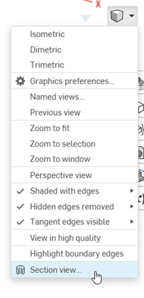
- パーツ/サーフェスは、上記のステップ 1 で選択したポイント (円筒面、円錐面、平面上の面、平面、合致コネクタのいずれか) で断面化されます。最後に選択した場所にマニピュレータが表示され、選択項目を一覧表示するダイアログが開きます。
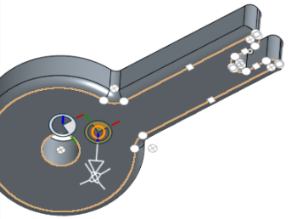
![ビューから断面を除外する際にモデルの 45 度回転を示した例を含む [断面ビュー] ダイアログ](../Resources/Images/concepts/sectionview-manip.png)
- マニピュレータの開いた円 (ボール) をクリックしドラッグして配置します。円柱の重心などの、パーツまたはアセンブリの任意の推測点にスナップできます (下の白いマークが推測点を示します)。
- マニピュレータを使用して、断面の深度や角度を変更します。
- 矢印を使用して深さを変更し、一方向または別の方向にドラッグします。マニピュレータをクリックして、ビューの方向を反転します。
- 角度インジケータを使用して、一定の角度でドラッグします。
- グラフィック領域で数値フィールドを使用して、ビューの深度または角度を入力します。
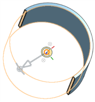
![断面を除外して 55 度回転した断面を示す [断面ビュー] ダイアログ](../Resources/Images/concepts/sectionview-angle.png)
- ダイアログボックスを開いたまま別のセクション平面を選択するには、新しいセクション平面の目的の場所をクリックします。[新しいマニピュレータとセクション平面] が表示されます。
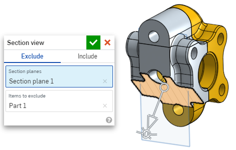
![ビューから除外された追加の断面を示す [断面ビュー] ダイアログ](../Resources/Images/concepts/sectionview-selectedplane.png)
断面ビュー平面に垂直な断面を表示するには、ショートカットキー N を使用するか、右クリックしてコンテキストメニューから [垂直に表示] を選択します。
- 1 つまたは複数のパーツ (サーフェス) を断面から除外するには、[除外するアイテム] フィールドをアクティブにし、グラフィック領域で次の項目を選択します。
-
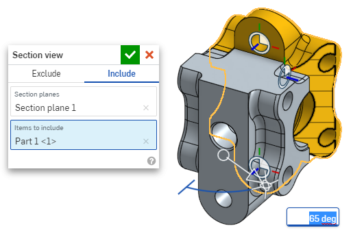
1 つまたは複数のパーツ (サーフェス) を断面に含めるには、[含める] タブを選択し、グラフィック領域で含める項目を選択します。
断面ビューでモデルを移動するには、ダイアログボックスの外をクリックして閉じ、必要に応じてモデルを操作します。
- ダイアログボックスで [既定の平面を選択] アイコン (
 ) をクリックし、グラフィック領域で既定の平面オプションを開きます。
![[既定の平面を選択] アイコンをクリックしたときのスクリーンショット](../Resources/Images/drawings/default-section-plane.png)
-
ドロップダウンメニューから既定の平面を選択すると、それに応じて断面ビューダイアログが更新されます。
オプションで、[平面を反転] アイコンをクリックすると、正面/背面、上/下、右/左のビューを簡単に切り替えることができます。
-
[平面を選択] オプションダイアログの緑のチェックマークをクリックして、既定の平面オプションを保存して閉じ、断面ビューダイアログボックスを開いたままにするか、断面ビューダイアログボックスの緑のチェックマークをクリックして両方のダイアログを保存して閉じます。
-
終了したら、[カメラとレンダリングのオプション] メニュー
またはコンテキストメニューから [断面ビューをオフにする] を選択します。
選択を行う前に、断面ビューをオンにすることもできます。
交差するパーツがある場合、それらは赤でレンダリングされます。
断面ビューがオフになっていない状態でダイアログボックスが閉じている場合は、セクション平面をダブルクリックしてダイアログをもう一度開きます。または、カメラとレンダリングのオプション ![]() をクリックするか、パーツまたはアセンブリを右クリックしてコンテキストメニューにアクセスし、[断面ビューを編集] を選択します。
をクリックするか、パーツまたはアセンブリを右クリックしてコンテキストメニューにアクセスし、[断面ビューを編集] を選択します。
断面ビューを使用して、ビューを名前付きビューとして保存できます。
断面ビューでは、面、エッジ、頂点に測定ツールを使用することもできます。詳細は、測定ツールおよびアセンブリ測定ツールを参照してください。