 Vista in sezione
![]()
![]()
![]()
Disponibile in: Part Studio, Assieme
La vista in sezione consente di selezionare uno o più piani o mate connector e una o più facce cilindriche, facce coniche o facce planari da utilizzare nella creazione di sezioni. Consente inoltre di selezionare un piano predefinito. La vista in sezione è attivabile tramite il menu Opzioni fotocamera e rendering o selezionando la vista in sezione nel menu contestuale.
Una volta che il manipolatore è visibile, può essere spostato tramite la sfera (cerchio aperto al centro) e agganciato a qualsiasi punto di deduzione sulla parte, sulla superficie o sull'assieme. Gli elementi sezionati sono visualizzabili sia nei Part Studio che negli assiemi:
- Seleziona uno o più piani, mate connector, facce cilindriche, facce coniche o facce planari per la parte o la superficie.
- Espandi il menu Opzioni fotocamera e rendering
 e seleziona Vista in sezione (mostrato sotto). In alternativa, fai clic con il pulsante destro del mouse su una parte nel Part Studio o su un assieme in una scheda Assieme e seleziona Vista in sezione nel menu contestuale.
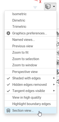
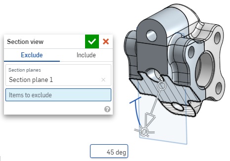
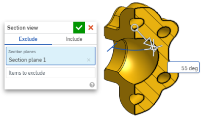
- La parte/superficie è sezionata nel punto scelto nel passaggio 1 precedente (faccia cilindrica, faccia conica, faccia planare, piano o mate connector). Un manipolatore appare nell'ultima posizione selezionata e si apre una finestra di dialogo elenca le selezioni:
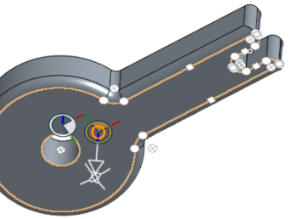
- Fai clic e trascina il cerchio aperto (sfera) del manipolatore per posizionarlo. Ricorda che puoi agganciarlo a qualsiasi punto di deduzione sulla parte o sull'assieme, anche ai centroidi dei cilindri (i contrassegni bianchi qui di seguito indicano i punti di deduzione):
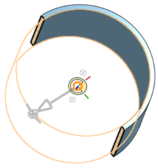
- Utilizza il manipolatore per modificare la profondità e/o l'angolo della sezione.
- Usa la freccia per modificare la profondità, trascinandola in una direzione o nell'altra. Fai clic sul manipolatore per invertire la direzione della vista.
- Usa gli indicatori angolari per trascinare gli elementi desiderati con un'angolazione specifica.
- Utilizza il campo numerico nell'area grafica per digitare la profondità o l'angolo della vista.
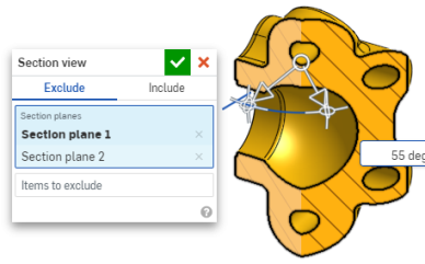
- Per selezionare un piano di sezionamento diverso mentre la finestra di dialogo rimane aperta, è sufficiente fare clic sulla posizione desiderata per il nuovo piano di sezionamento: tale operazione visualizza un nuovo manipolatore e un nuovo piano di sezione.
Per visualizzare la sezione normale al piano della vista in sezione, utilizza il tasto di scelta rapida N oppure fai clic con il pulsante destro del mouse e seleziona la vista Normale a nel menu contestuale.
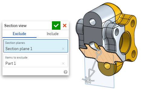
- Per escludere una o più parti (superficie o superfici) dalla selezione, attiva il campo Elementi da escludere, quindi effettua le selezioni desiderate nell'area grafica:
-
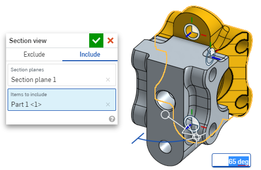
Per includere una o più parti (superficie o superfici) nella sezione, seleziona la scheda Includi, quindi seleziona gli elementi da includere nell'area grafica:
Per spostare il modello mentre si è nella vista in sezione, fai clic all'esterno della finestra di dialogo per chiuderla, quindi manipola il modello nel modo desiderato.
- Fai clic sull'icona Seleziona piano predefinito
 nella finestra di dialogo per aprire le opzioni del piano predefinito nell'area grafica:
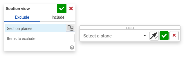
-
Seleziona un piano predefinito dal menu a discesa: la finestra di dialogo Vista in sezione si aggiorna di conseguenza.
Se necessario, fai clic sull'icona Inverti piano per alternare facilmente tra le viste anteriore/posteriore, superiore/inferiore o da destra/da sinistra.
-
Fai clic sul segno di spunta verde nella finestra di dialogo delle opzioni di Seleziona un piano per salvare e chiudere le opzioni predefinite, mantenendo aperta la finestra di dialogo Vista in sezione. Fai clic sul segno di spunta verde nella finestra di dialogo Vista in sezione per salvare e chiudere entrambe le finestre di dialogo.
-
Al termine, seleziona Disattiva vista in sezione nel menu Opzioni fotocamera e rendering
o nel menu contestuale.
Puoi anche attivare Vista in sezione prima di effettuare qualsiasi selezione.
Se esistono parti che si intersecano, queste sono renderizzate in rosso.
Se la vista in sezione non è disattivata e la finestra di dialogo è chiusa, aprite nuovamente la finestra di dialogo facendo doppio clic sul piano di sezione. In alternativa, fate clic sul menu Fotocamera e opzioni di rendering ![]() oppure fate clic con il pulsante destro del mouse sulla parte o sull'assieme per accedere al menu contestuale e selezionate Modifica vista in sezione.
oppure fate clic con il pulsante destro del mouse sulla parte o sull'assieme per accedere al menu contestuale e selezionate Modifica vista in sezione.
È possibile utilizzare la vista Sezione e quindi salvare la vista come vista con nome.
È inoltre possibile utilizzare lo strumento Misura su facce, bordi e vertici all'interno di una vista in sezione. Consulta Strumento di misura per ulteriori informazioni.