 Etiqueta
![]()
Etiquete entidades de perfil de boceto para usarlas en marcos o piezas a fin de agregarlas o quitarlas de formas de chapa metálica. Seleccione la geometría, defina la orientación y agregue propiedades.
Onshape proporciona una biblioteca de perfiles estructurales estándar integrados directamente en la operación Frame. Sin embargo, puede haber ocasiones en las que necesite crear una biblioteca personalizada de perfiles de marco. Es muy fácil crear y compartir perfiles personalizados para usarlos con la operación Frames. En este video se explica cómo hacerlo definiendo una biblioteca de bocetos, configurando el perfil para diferentes opciones de tamaño y etiquetando el perfil para que la tabla de la Lista de cortes se complete con los segmentos y las propiedades de los segmentos.
Para crear una nueva biblioteca de perfiles, cree un nuevo documento de Onshape. Organice los perfiles en uno o más documentos de la biblioteca. Coloque el documento de la biblioteca en una carpeta en la raíz de la Company o Enterprise. Esta práctica facilita el uso compartido con otros usuarios que necesitan usar los perfiles.
Cree un boceto del perfil en un Part Studio. Cree un Part Studio único para cada boceto de perfil. Durante la creación del boceto, tenga en cuenta cómo quiere alinear el perfil. Si es necesario, agregue puntos de boceto que sirvan como puntos de alineación adicionales. Defina el boceto con cotas y relaciones. Utilice variables al definir las cotas del boceto que quiere configurar para las diferentes opciones de tamaño de perfil. Las variables facilitan la identificación de los valores esenciales del perfil. Cambie el nombre del Part Studio y del boceto para describir el perfil. El nombre único hace que sea más fácil para los usuarios entender la intención de su perfil. Cuando se selecciona el perfil, el nombre del Part Studio aparece en la parte superior del cuadro de diálogo, y el nombre del boceto en la parte inferior.
Si el perfil está disponible en varios tamaños diferentes con la misma forma, configure las cotas del boceto o los valores variables. Cree tablas de configuración con los ajustes de configuración para cada tamaño. Luego, configure las cotas o variables, si se utilizan. Edite el boceto, haga clic derecho en cada cota para controlar la configuración y seleccione Configurar cota. Si define el boceto con variables, edite la variable, haga clic derecho en el valor y seleccione Configurar. Edite los valores de la tabla de configuración.
A continuación, inicie una nueva operación Etiqueta y seleccione Frame en el menú desplegable. La operación Etiqueta agrega propiedades al perfil, de modo que, cuando se usa en una operación Frame, la tabla de la Lista de cortes incluye los encabezados de las columnas, como Estándar y Descripción, y completa los valores de esas propiedades.
Seleccione el perfil del boceto. Puede seleccionarlo en el área gráfica o en la Lista de operaciones. Si se requieren puntos de alineación adicionales, expanda el campo de selección y seleccione puntos en el boceto para que sirvan como puntos de alineación. Luego, ingrse cadenas numéricas o de texto para Estándar y Descripción. Si estos campos se dejan en blanco, esa columna no se agrega a la Lista de cortes cuando se usa el perfil, o esa celda muestra el mensaje «No establecido» si otros perfiles utilizados en la estructura tienen ese encabezado de columna definido. Los ajustes Estándar y Descripción se pueden configurar. Haga clic derecho en el campo del cuadro de diálogo Perfil de etiqueta y seleccione Configurar. A continuación, edite las celdas de la Tabla de configuración.
Para proporcionar más propiedades al perfil, haga clic en Agregar columna e ingrese la información del encabezado y el valor. Repita el procedimiento según sea necesario para agregar más columnas a la tabla de la Lista de cortes. Haga clic en la marca de verificación cuando haya terminado. Estas propiedades no se pueden configurar. Haga clic en el botón Eliminar (X) del cuadro de diálogo para quitar una columna.
Haga clic en la marca de verificación para aceptar la operación Etiqueta. Este perfil ahora se puede usar con las estructuras contenidas en este documento. Inicie una nueva operación Frame en otro Part Studio y haga clic en la selección del perfil de boceto en el cuadro de diálogo. En el documento actual, seleccione el perfil. Ajuste la configuración y haga clic en Generar para aplicar los valores configurados. Luego, seleccione el perfil de boceto.
Cuando cree bibliotecas de perfiles personalizados, guarde los perfiles en un documento diferente al de los diseños que las utilizan. En este caso, cree una versión para el documento que contiene los perfiles una vez completado. A partir de ese momento, se puede hacer referencia al perfil mediante documentos vinculados. En este ejemplo, un documento diferente contiene los perfiles personalizados. Haga clic en Otros documentos, navegue hasta el documento y seleccione el perfil de boceto.
Para permitir a otros usuarios acceder a perfiles personalizados, se debe compartir el documento o la carpeta que contiene los perfiles. Los usuarios que necesitan hacer referencia a perfiles personalizados de la operación Frames solo necesitan permisos de visualización y vinculación. Los usuarios que ayudan a administrar perfiles personalizados necesitan permisos de edición y vinculación. Usar equipos para compartir es una excelente manera de garantizar que las personas adecuadas tengan acceso y facilita la administración del acceso. Cuando se producen cambios de personal en la organización, es más fácil administar la adición o eliminación de usuarios de un equipo que en los recursos compartidos individuales.
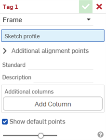
Para etiquetar un perfil que ha creado o modificado y usar la información de la tabla de la Lista de cortes como columnas adicionales, haga lo siguiente:
- Click the Tag icon (
 ) to open the Tag dialog:
-
Seleccione Marco a los fines de la etiqueta
- En el campo Perfil de boceto, seleccione el boceto en la Lista de operaciones, que sirve como boceto para el perfil.
-
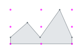
Por defecto, la opción Mostrar puntos predeterminados está habilitada en el cuadro de diálogo. Esto coloca una rejilla de alineación de 9 puntos de color magenta superpuesta en el perfil del boceto. Desactive esta opción para ocultar los puntos de alineación.
-
En el campo Puntos de alineación adicionales, seleccione cualquier otro punto del boceto que desee utilizar para la alineación.
- En el campo Estándar, ingrese el valor que se mostrará en la columna Estándar de la tabla de la Lista de cortes.
- En el campo Descripción, ingrese una descripción para mostrar en la columna Descripción de la tabla de la Lista de cortes.
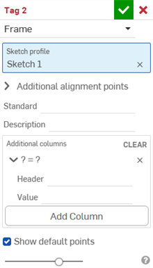
- A fin de proporcionar más columnas de información para el perfil, haga clic en Agregar columna:
-
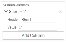
En el campo Encabezado, ingrese el nombre del nuevo encabezado de columna que aparecerá en la tabla de la Lista de cortes del perfil adicional y el valor:
-
Haga clic en Agregar columna para agregar otro par de columna/valor a la tabla de la Lista de cortes.
-
Haga clic en la marca de verificación (
 ).
).
El procedimiento recomendado consiste en etiquetar un perfil, crear una versión y hacer referencia a esa versión del perfil en el marco.

Observe los nuevos valores en la columna Descripción y la columna adicional 'Corto' con los valores correspondientes, arriba.
La nueva información del perfil aparece en la tabla Lista de cortes después de usarla en una operación de marco, seguida de una operación de tabla de lista de cortes para crear la tabla. Haga clic en ![]() en el lado derecho de la ventana para abrir el panel de la tabla.
en el lado derecho de la ventana para abrir el panel de la tabla.
Las etiquetas de formas designan las piezas que no son de chapa metálica para utilizarlas como operaciones de forma a fin de agregar o quitar material del modelo de chapa metálica.
Para etiquetar piezas, haga lo siguiente:
- Haga clic en el ícono de etiqueta (
 ) para abrir el cuadro de diálogo Etiqueta:
-
Seleccione Forma a los fines de la etiqueta:
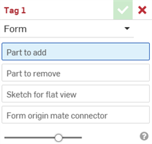
- En el campo Pieza para agregar, seleccione la pieza de la Lista de piezas o del área gráfica desde el que desea agregarla a la chapa metálica.
- En el campo Pieza para quitar, seleccione la pieza de la Lista de piezas o del área gráfica de el que desea sustraer la chapa metálica.
- Seleccione el boceto para la vista plana. Este es el boceto utilizado para la vista plana del Modelo de chapa metálica.
- Seleccione el conector de relación de origen de la forma. Esto determina la dirección en la que se modela la forma en el modelo de chapa metálica. Coloque el cursor sobre el modelo en el área gráfica para seleccionar un conector de relación implícito o explícito. Si no se selecciona ninguno, la operación crea uno en el origen del Part Studio.
- Haga clic en la marca de verificación (
 ).
).
No seleccione una pieza de chapa metálica. Seleccione una pieza geométrica convencional.
No seleccione una pieza de chapa metálica. Seleccione una pieza geométrica convencional.
Solo puede haber una operación de etiquetado de forma válida por Part Studio. Cree una forma por Part Studio.
-
 Marco: cree una colección de cuerpos barridos que compartan un perfil, ordenados de extremo a extremo.
 -
 Recorte de marco: recorta los segmentos como grupos ordenados.
 -
 Cartela: sirve para crear cartelas entre los segmentos de marco adyancentes.
 -
 Tapa final: crea una o más tapas finales para los segmentos de marcos.
 -
 Lista de cortes: crea una lista de cortes de todos los segmentos de un marco con sus características. Esta operación también crea una pieza compuesta abierta para la colección.
 -
 Etiqueta: etiquete entidades de perfil de boceto para usarlas en marcos o piezas y sumar o restar de formas de chapa metálica. Seleccione la geometría, defina la orientación y agregue propiedades.