 Vista de sección
![]()
![]()
![]()
Disponible en: Part Studio, Ensamblaje
Desde la vista de sección, puede seleccionar uno o varios planos, conectores de relación, caras cilíndricas, caras cónicas o caras planas a fin de utilizarlos en la sección. También se puede utilizar para seleccionar un plano predeterminado. La vista de sección se puede activar a través del menú Opciones de cámara y representación o al seleccionar Vista de sección en el menú contextual.
Una vez que el manipulador está visible, se puede mover a través de la bola (círculo abierto en su centro) y se puede enganchar a cualquier punto de inferencia de la pieza, la superficie o el ensamblaje. Los elementos seccionados se pueden ver tanto en los Part Studios como en los Ensamblajes:
- Seleccione uno o varios planos, conectores de posición, caras cilíndricas, caras cónicas o caras planas en la pieza o superficie.
- Expanda el menú de Opciones de cámara y representación
 y seleccione Vista de sección (se muestra a continuación). También puede hacer clic derecho en una pieza del elemento Part Studio o en un ensamblaje en una pestaña Ensamblaje y seleccionar Vista de sección en el menú contextual.
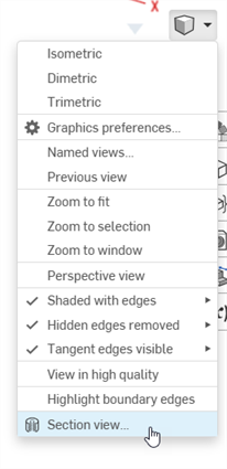
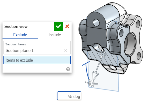
- La pieza/superficie se secciona en el punto elegido en el paso 1 anterior (cara cilíndrica, cara cónica, cara plana, plano o conector de relación). Aparece un manipulador en la última ubicación seleccionada y se abre un cuadro de diálogo con las selecciones:
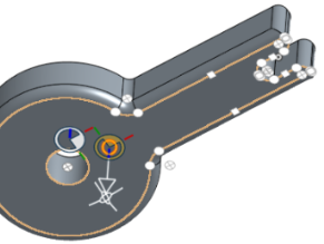
- Haga clic y arrastre el círculo abierto (bola) del manipulador para ubicarlo en posición. Observe que puede ajustarlo a cualquier punto de inferencia de la pieza o ensamblaje, incluidos los centroides de los cilindros (las marcas blancas a continuación indican puntos de inferencia):
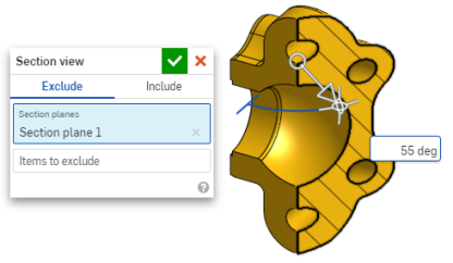
- Utilice el manipulador para cambiar la profundidad y/o el ángulo de la sección.
- Utilice la flecha para cambiar la profundidad y arrastre en una dirección u otra. Haga clic en el manipulador para voltear la dirección de la vista.
- Utilice los indicadores de ángulo para arrastrar en un ángulo.
- Utilice el campo numérico del área gráfica para escribir la profundidad o el ángulo de la vista.
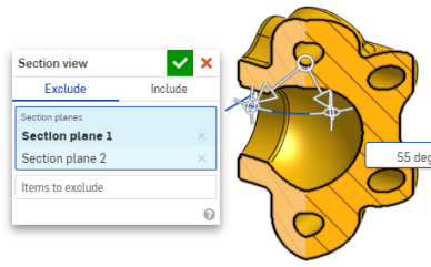
- Para seleccionar un plano de sección diferente mientras el cuadro de diálogo permanece abierto, haga clic en la ubicación que desea para el nuevo plano de sección y aparecerá un nuevo manipulador y plano de sección.
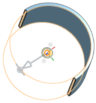
Para ver la sección normal al plano de vista de sección, utilice la tecla de acceso directo N o haga clic con el botón derecho del mouse y seleccione Ver normal a en el menú contextual.
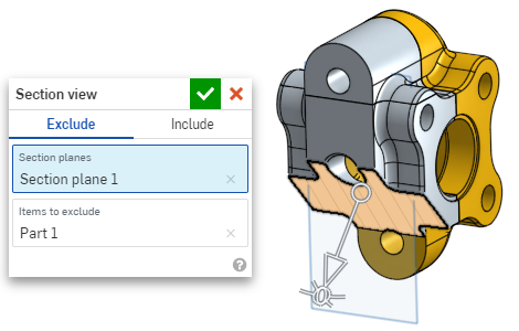
- Para excluir una o varias piezas (/superficie o superficies) de la sección, active el campo Elementos a excluir y haga sus selecciones en el área gráfica:
-
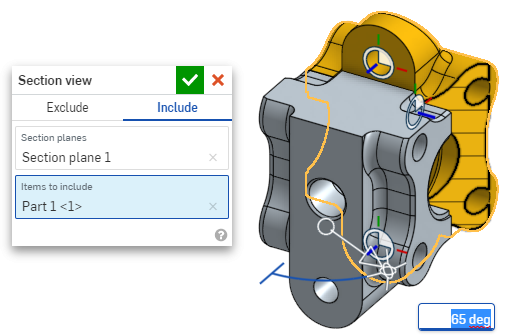
Para incluir una o varias piezas (/superficie o superficies) en la sección, seleccione la pestaña Incluir y, a continuación, los elementos que desea incluir en el área gráfica:
Para mover el modelo mientras se encuentra en la vista de sección, haga clic fuera del cuadro de diálogo para cerrarlo y, a continuación, manipule el modelo del modo deseado.
- Haga clic en el ícono de seleccionar plano predeterminado
 del cuadro de diálogo para abrir las opciones de plano predeterminadas en el área gráfica:
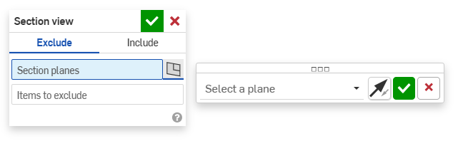
-
Seleccione un plano predeterminado del menú desplegable y el cuadro de diálogo Vista de sección se actualizará según corresponda.
Si lo desea, haga clic en el ícono de voltear plano para cambiar fácilmente entre las vistas frontal/posterior, superior/inferior o derecha/izquierda.
-
Haga clic en la marca de verificación verde del cuadro de diálogo Seleccionar un plano para guardar y cerrar las opciones de plano predeterminadas, pero mantener abierto el cuadro de diálogo Vista de sección. O bien, haga clic en la marca de verificación verde del cuadro de diálogo Vista de sección para guardar y cerrar ambos cuadros de diálogo.
-
Cuando haya terminado, seleccione Desactivar vista Sección desde el menú Opciones de cámara y representación
o el menú contextual.
También puede activar la vista Sección antes de realizar cualquier selección.
Si existen partes que se intersecan, se renderizan en rojo.
Si la vista Sección no está desactivada y el cuadro de diálogo está cerrado, vuelva a abrir el cuadro de diálogo; para ello, haga doble clic en el plano de sección. También puede hacer clic en el menú Opciones de cámara y representación ![]() o hacer clic derecho en la pieza o el ensamblaje para acceder al menú contextual y seleccionar Editar vista Sección.
o hacer clic derecho en la pieza o el ensamblaje para acceder al menú contextual y seleccionar Editar vista Sección.
Puede utilizar la vista Sección y, a continuación, guardar la vista como vista con nombre.
También puede utilizar la herramienta Medir en caras, aristas y vértices en una vista de sección. Consulte Herramienta Medir para obtener más información.