


iOS and Android support for the sheet metal Jog feature is limited to viewing and editing jogs that are created from the desktop (browser) platform.
Disponible en: elemento Part Studio, ensamblaje
Offset a sheet metal model at a reference line with two bends in opposite directions with additional jog controls to define its offset, angle, alignment, and orientation. The result forms an S- or Z-shaped curve in the sheet metal.
A jog is often used where two pieces of sheet metal come together, and a flush seam is desired. A jog can be placed along edges, surfaces, or at specific locations on the sheet metal part.
 Pasos
Pasos
To create a jog:
- While in a Part Studio, click the Sheet metal jog icon (
 ) on the Feature toolbar.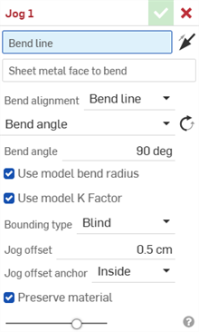
- Select the Bend line in the Graphics area where the jog should occur.
- Select the Sheet metal face to bend. Only one face can be jogged per feature.
- Click the Hold opposite side arrow (
 ) to jog the opposite side of the sheet metal face.
Default side (left), Hold opposite side (right)
- Select the Bend alignment:
- Bend line - Align the bend line to the middle of the jog in the sheet metal flat pattern.
- Hold line - Align the bend line to the start of the jog in the sheet metal flat pattern.
- Hold other line - Align the bend line to the end of the jog in the sheet metal flat pattern.
- Inner - Align the inside of the bent wall with the bend line.
- Outer - Align the outside of the bent wall with the bend line.
- Middle - Align the mid-plane of the bent wall with the bend line.
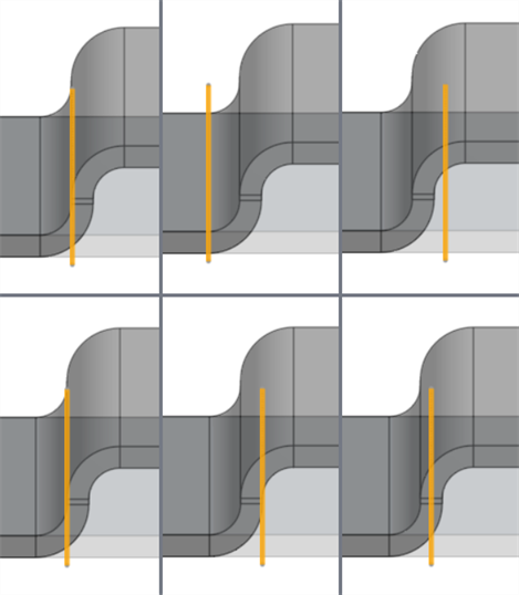
Bend alignment examples with Bend line highlighted orange: Bend line (top left), Hold line (top middle), Hold other line (top right), Inner (bottom left), Outer (bottom middle), Middle (bottom right)
- Select a Angle control type:
Ángulo de pliegue: alinea el pliegue en paralelo a la línea de pliegue.
Ángulo de pliegue: ingrese un ángulo de pliegue de 1 a 359 grados desde la línea de pliegue. Si lo desea, haga clic en Ángulo opuesto (
 ) para voltear el ángulo de pliegue.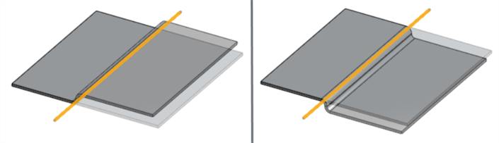
Ángulo de pliegue: 90 grados; ángulo predeterminado (izquierda), ángulo opuesto (derecha); línea de pliegue resaltada en naranja.
Alinear con la geometría: alinea el pliegue en paralelo a la geometría seleccionada.
Parallel to - Select an edge, face, or plane for the bend's parallel alignment.
Align from direction - Align the bend directionally from the selected geometry. Use the Opposite direction angle arrow (
) to flip the angle's direction.Dirección: seleccione una arista, una cara o un plano para la alineación direccional del pliegue.
Ángulo: ingrese el ángulo de pliegue de 1 a 180 grados desde la arista, la cara o el plano de dirección seleccionado.
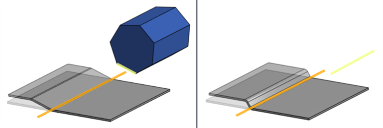
Left: bend line (orange) aligned to geometry (parallel to the yellow polygon edge); Right: Bend line (orange) angled from direction (yellow sketch line)
-
Keep Use model bend radius checked to use the inside bend radius specified for the sheet metal model, or leave unchecked to enter a custom Bend radius value.
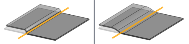
Left: Use model bend radius checked (0.23 cm); Right: Use model bend radius unchecked (Bend radius: 2.5 cm)
-
Keep Use model K factor checked to use the Sheet metal model Feature's K factor value, or leave unchecked to enter a custom K Factor value.
-
Select a Bounding type:
-
Blind - Offset the jog to a specified distance in the Jog offset field.
-
Up to entity - Offset the jog to a specified entity. Check Offset distance and enter an additional distance to offset beyond the selected entity.

The bottom of the sheet metal jog is bounded up to the opposing sheet metal's top face (in yellow)
-
Thickness - Enter a Thickness factor to offset the jog by a factor of the Sheet metal model's Thickness parameter. For example, if the Sheet metal model's Thickness is 0.5 cm, a Thickness factor of 4 offsets the jog by 2 cm.
-
-
Select the Jog offset anchor to define how the height of the jog is measured relative to the sheet metal face:
-
Inside - Defines the distance from the top sheet metal face to the inner parallel surface of the jog (shortest distance).
-
Nominal - Defines the distance from the bottom of the sheet metal face to the outer surface of the jog. This accounts for the overall height of the profile and is also called the Overall dimension.
-
Outside - Defines the distance from the top sheet metal face to the outer parallel surface of the jog.
-
-
With Preserve material checked (default), no additional sheet metal material is added as a result of the jog. Uncheck to add material to the sheet metal to compensate for the jog. This maintains the sheet metal's original length before the jog was applied.
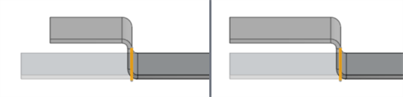
Left: Preserve material checked; Right: Preserve material unchecked
- Click the checkmark (
 ) to accept the Jog feature.
To modify a Jog after it is created, use a direct edit tool such as Move face.
Notas
Línea de pliegue
La línea de pliegue no indica necesariamente la línea en la que se produce el pliegue.
-
No tiene que coincidir con la cara seleccionada. Se proyecta en la cara.
-
No tiene que cortar completamente la cara seleccionada. Se alarga hasta las aristas de la cara.
-
No tiene que formar parte de ningún boceto.
-
Se puede extender a lo largo de varios cortes en la misma cara.
-
En la mayoría de los casos, puede ser cualquier ángulo con respecto a la cara seleccionada. En algunos casos con una geometría de referencia compleja, se produce un error.
General
-
Un pliegue no puede interferir con ninguna operación anterior de pliegue o esquina de la lista de operaciones. Esto provoca una colisión en el modelo de chapa metálica y produce un error. Sin embargo, puede crear pliegues en las caras de las bridas y los dobladillos.
-
El uso de un valor de factor K personalizado modifica la longitud efectiva del metal plegado solo en el modelo 3D.
-
El valor de tolerancia de pliegue o deducción de pliegue no se puede editar desde el cuadro de diálogo Pliegue. Ajuste este valor en la operación Modelo de chapa metálica o abra la tabla Chapa metálica y la vista plana y haga doble clic en la celda de la tabla para editar el valor directamente. Consulte Edición de chapa metálica en la tabla.
-
The bend does not affect dimensions of the Sheet metal flat pattern if Preserve material is checked.
Ejemplos
Overlap
-
The jog is created in the middle of one of the ends of the sheet metal sides (Bend line in orange), with a 0.01 cm Offset distance, to prevent sheet metal collision:
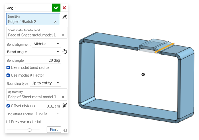
-
A Move face feature is then created to move the opposing sheet metal end face beneath and up to the edge of the jog (Face to move in orange; Up to entity in yellow):
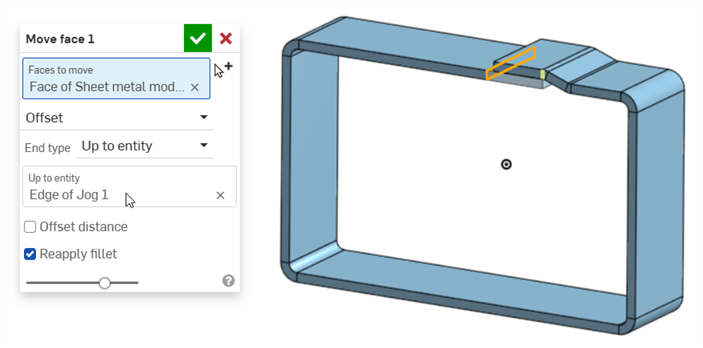
Circular sheet metal jog
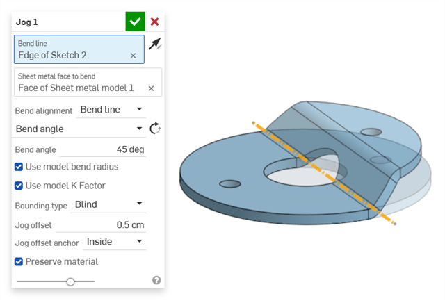
Example adding a jog on a washer:
Sleeve insert
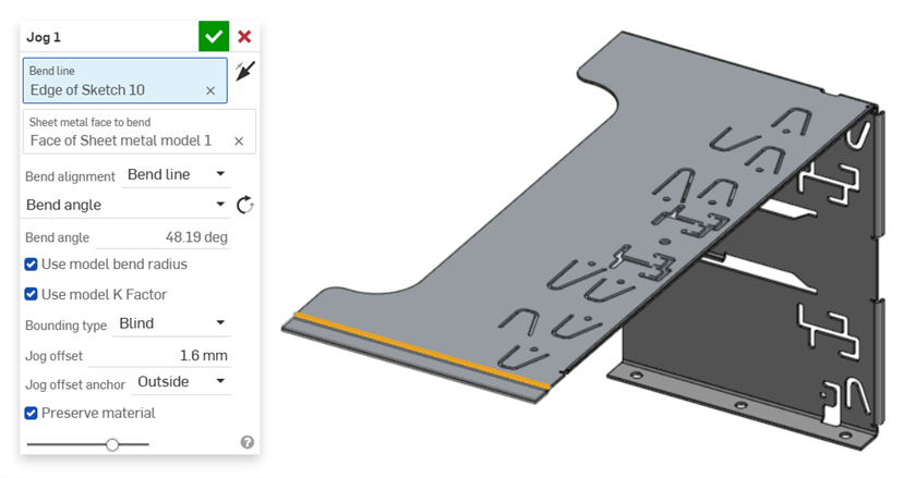
Example of a jog used on the edge of a metal case sleeve insert:
Herramientas de chapa metálica adicionales
Cuando un modelo de chapa metálica está activo (en el proceso de creación o edición), hay herramientas adicionales disponibles:
-
 Brida: cree una pared para cada arista seleccionada, conectada a la arista seleccionada con un pliegue.
 -
 Dobladillo: cree un dobladillo para cada arista o cara seleccionada en una pieza de chapa metálica existente.
 -
 Pestaña: añada una pestaña a una brida de chapa metálica.
 -
 Pliegue: pliegue un modelo de chapa metálica a lo largo de una línea de referencia, con opciones de control de pliegue adicionales.
 -
Jog - Offset a sheet metal model at a reference line with two bends in opposite directions with additional jog controls to define its offset, angle, alignment, and orientation. The result forms an S- or Z-shaped curve in the sheet metal.
-
 Forma: crea operaciones de formas en modelos de chapa metálica existentes. Las formas se pueden seleccionar del documento actual, de otros documentos o de una biblioteca predefinida de formas de chapa metálica.
 -
 Solevación: permite crear modelos de chapa metálica que conecten dos perfiles.
 -
 Crear unión: convierta la intersección de dos paredes en una operación de unión, ya sea un pliegue (paredes unidas por una geometría cilíndrica) o una rasgadura (pequeño espacio entre dos paredes).
 -
 Esquina: modifique el tipo de esquina y la escala de liberación.
 -
 Liberación de pliegue: modifique una liberación de pliegue (el pequeño corte que se hace donde el extremo del pliegue se une al pliegue libre), la profundidad y el ancho de liberación.
 -
 Modificar unión: realice cambios en una unión existente, como convertir un pliegue en una rasgadura. Disponible actualmente a través de la tabla de vista plana.
 -
 Corte de esquina: corta la esquina de las piezas de chapa metálica existentes aplicando un redondeo o un chaflán. Seleccione el vértice o la arista de una esquina y especifique el tipo de Corte de esquina y la distancia. Se recomienda utilizar esta operación una vez finalizadas todas las bridas y juntas del modelo de chapa metálica.
 -
 Tabla de chapa metálica y vista plana: abra y cierre las tablas Rasgadura/Pliegue y visualice el patrón plano del modelo de chapa metálica. Utilice esta tabla para convertir rasgaduras en pliegues y viceversa.
 -
 Acabar modelo de chapa metálica: cierra (desactiva) el modelo de chapa metálica y crea una operación en la lista de operaciones.