 Solevación de chapa metálica
![]()
![]()
![]()
La compatibilidad de iOS y Android con la operación de solevación de chapa metálica se limita a la visualización y edición de solevación que se crean desde la plataforma de escritorio (navegador).
Disponible en: elemento Part Studio, ensamblaje
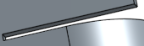
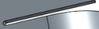
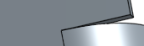
Permite crear una pieza de chapa metálica que haga la transición entre dos perfiles.
Para crear una solevación de chapa metálica:
- Cuando un elemento Part Studio abierto, haga clic en el botón Solevación de chapa metálica (
 ).
).
- Seleccione Nuevo para crear una nueva pieza de chapa metálica o seleccione Añadir para añadir la solevación a una pieza existente.
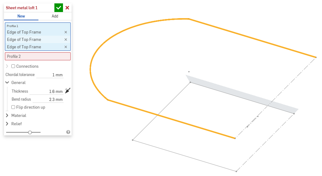
- Con el foco en el campo Perfil 1, seleccione el perfil inicial (región, cara, arista o punto).
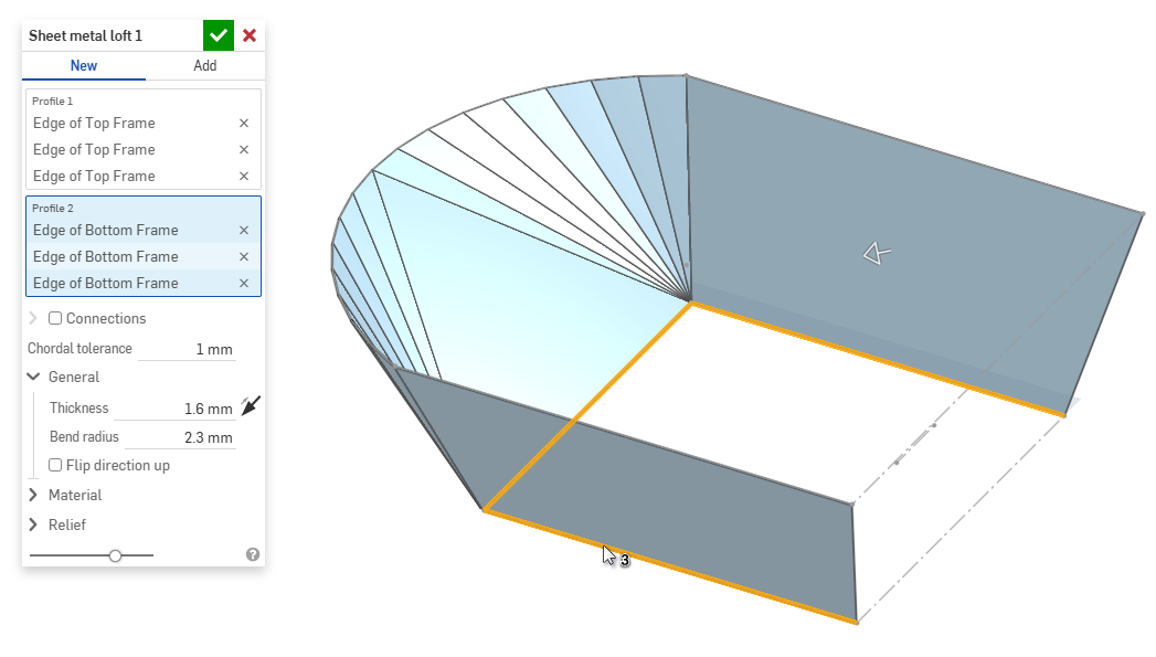
- Con el foco en el campo Perfil 2, seleccione el perfil final. Onshape crea un modelo de chapa metálica entre los dos perfiles.
- Haga clic en la casilla de verificación Conexiones para tener más control sobre la torsión del modelo resultante. Onshape estima la proximidad dentro de los vértices o las aristas existentes si no se especifica ninguna coincidencia.
- Seleccione un vértice o una arista de la solevación y arrastre los manipuladores para ajustar la conexión.
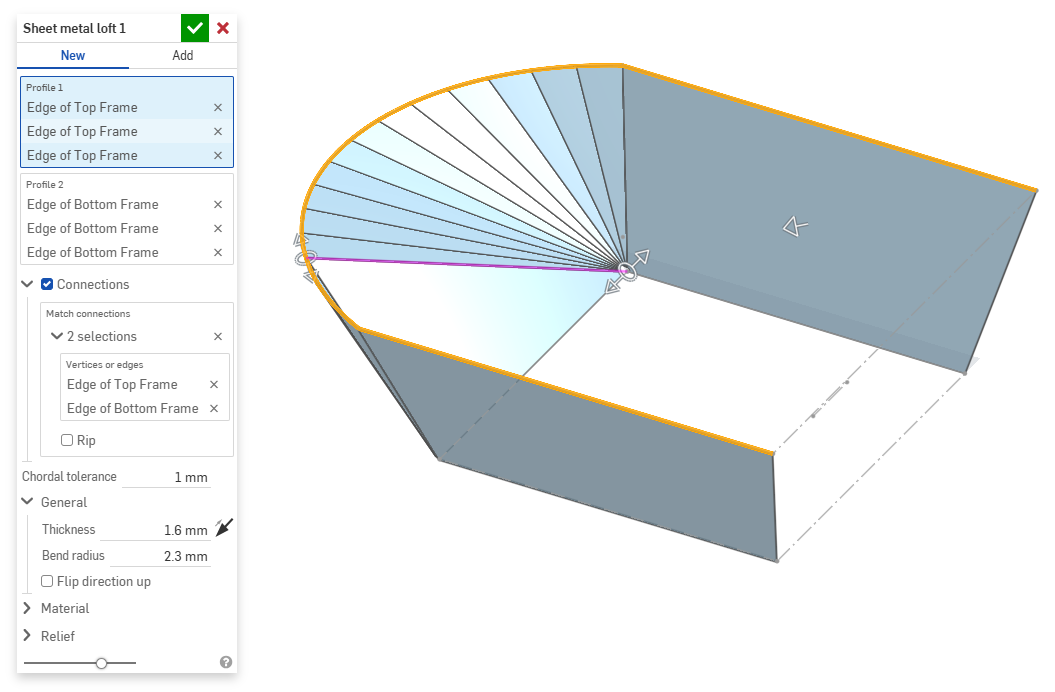
- Para dividir el modelo en partes independientes en la conexión, seleccione Rasgadura.
- Seleccione un vértice o una arista de la solevación y arrastre los manipuladores para ajustar la conexión.
- Utilice el campo Tolerancia cordal para definir la distancia máxima que la geometría teselada puede variar con respecto a la superficie subyacente.
- Al crear nuevos modelos de chapa metálica, también puede expandir las siguientes secciones para refinar aún más el modelo:
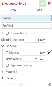
- General:
- Espesor: espesor de la chapa metálica. Haga clic en la flecha para invertir la dirección.
- Radio de pliegue: el radio interior de los pliegues creados.
- Voltear la dirección hacia arriba: permite invertir la orientación del modelo de chapa metálica y la vista plana. Esto resulta útil para definir si los pliegues están hacia arriba o hacia abajo, en relación con el modelo.
- Material (las opciones de esta sección son idénticas a las que se proporcionan en la operación Modelo de chapa metálica):
- Cálculo de pliegue: determina cómo se calculan los pliegues. Las opciones son las siguientes:
- Factor K (predeterminado): utiliza la relación entre el eje neutro y el espesor del material.
- Tolerancia de pliegue: usa la longitud del arco de línea neutra entre los puntos tangentes de un pliegue.
- Deducción de pliegue: utiliza la diferencia entre la suma de las longitudes de las bridas (desde el arista hasta el ápice) y la longitud plana inicial.
El cálculo de pliegue seleccionado aquí se utiliza como columna en la tabla de chapa metálica. Cada pliegue se puede personalizar y editar directamente desde la tabla. Consulte Tabla de chapa metálica y vista plana para obtener más información.
- Factor K de pliegue predeterminado: es la fracción del espesor del material sobre la que se encuentra el eje neutro en un pliegue. (El valor predeterminado es 0,45).
- Factor K de enrollado: es la fracción del espesor del material sobre el que se encuentra el eje neutro en una sección de la pared laminada. (El valor predeterminado es de 0,5).
- Cálculo de pliegue: determina cómo se calculan los pliegues. Las opciones son las siguientes:
- Liberación (las opciones de esta sección son idénticas a las que se proporcionan en la operación Modelo de chapa metálica):
- Holgura mínima: la menor holgura entre las aristas de la chapa metálica que definen una rasgadura.
- Tipo de desahogo de esquina:
- Cuadrado: con tamaño definido
Vista plana:
 Vista 3D:
- Rectángulo: escalado
Vista plana:
 Vista 3D:
- Redondo: con tamaño definido
Vista plana:
 Vista 3D:
- Redondo: escalado
Vista plana:
 Vista 3D:
- Closed
Vista plana:
 Vista 3D:
- Simple
Vista plana:
 Vista 3D:
- Cuadrado: con tamaño definido
- Escala de desahogo de esquina: es la escala de apertura de la esquina (para esquinas escaladas); un valor entre 1,00 y 2,00.
- Tipo de liberación de pliegue: es la forma de la liberación de pliegue:
- Rectángulo - En escala
- Obround - Escalado
- Rasgadura
- Rectángulo - En escala
- Escala de profundidad de liberación de pliegue: un valor entre 1,00 y 5,00. Una vez introducido un valor, se convierte en el valor predeterminado en todos los documentos.
- Un valor de 1 da como resultado una liberación de pliegue de ojal que toca perfectamente el pliegue y una liberación de pliegue rectangular coincide con la profundidad del pliegue del ojal.
- Cualquier valor más allá de 1 añade profundidad mediante la siguiente fórmula:
(depth scale -1) * bendRadius
- Escala de ancho de liberación de pliegue: un valor entre 0,0625 y 2,00. Una vez introducido un valor, se convierte en el valor predeterminado en todos los documentos. El ancho de la liberación de pliegue se calcula mediante la siguiente fórmula:
thickness * width scale.
- General:
- Al añadir a un modelo de chapa metálica existente, haga clic en el campo Ámbito de combinación y, a continuación, seleccione la pieza a la que desee añadirla. El ámbito de combinación solo puede aceptar cuerpos de un único modelo de chapa metálica activo.
Cuando un modelo de chapa metálica está activo (en el proceso de creación o edición), hay herramientas adicionales disponibles:
-
 Brida: cree una pared para cada arista seleccionada, conectada a la arista seleccionada con un pliegue.
 -
 Dobladillo: cree un dobladillo para cada arista o cara seleccionada en una pieza de chapa metálica existente.
 -
 Pestaña: añada una pestaña a una brida de chapa metálica.
 -
 Pliegue: pliegue un modelo de chapa metálica a lo largo de una línea de referencia, con opciones de control de pliegue adicionales.
 -
 Forma: crea operaciones de formas en modelos de chapa metálica existentes. Las formas se pueden seleccionar del documento actual, de otros documentos o de una biblioteca predefinida de formas de chapa metálica.
 -
Solevación: permite crear modelos de chapa metálica que conecten dos perfiles.
-
 Crear unión: convierta la intersección de dos paredes en una operación de unión, ya sea un pliegue (paredes unidas por una geometría cilíndrica) o una rasgadura (pequeño espacio entre dos paredes).
 -
 Esquina: modifique el tipo de esquina y la escala de liberación.
 -
 Liberación de pliegue: modifique una liberación de pliegue (el pequeño corte que se hace donde el extremo del pliegue se une al pliegue libre), la profundidad y el ancho de liberación.
 -
 Modificar unión: realice cambios en una unión existente, como convertir un pliegue en una rasgadura. Disponible actualmente a través de la tabla de vista plana.
 -
 Corte de esquina: corta la esquina de las piezas de chapa metálica existentes aplicando un redondeo o un chaflán. Seleccione el vértice o la arista de una esquina y especifique el tipo de Corte de esquina y la distancia. Se recomienda utilizar esta operación una vez finalizadas todas las bridas y juntas del modelo de chapa metálica.
 -
 Tabla de chapa metálica y vista plana: abra y cierre las tablas Rasgadura/Pliegue y visualice el patrón plano del modelo de chapa metálica. Utilice esta tabla para convertir rasgaduras en pliegues y viceversa.
 -
 Acabar modelo de chapa metálica: cierra (desactiva) el modelo de chapa metálica y crea una operación en la lista de operaciones.