 Schnittansicht
![]()
![]()
![]()
Verfügbar in: Part Studios, Baugruppen
In der Schnittansicht können Sie eine oder mehrere Ebenen, Verknüpfungsverbindungen, zylindrische Flächen, konische Flächen oder ebene Flächen für die Schnittdarstellung auswählen. Außerdem können Sie hier eine Standardebene auswählen. Die Schnittansicht lässt sich über das Menü Kamera und Rendering-Optionen oder durch Auswählen der Schnittansicht im Kontextmenü aktivieren.
Sobald der Manipulator sichtbar ist, können Sie ihn über die Kugel (offener Kreis in der Mitte) bewegen und an einem beliebigen Ableitungspunkt auf dem Bauteil, der Oberfläche oder der Baugruppe einrasten lassen. Abgeschnittene Elemente können sowohl in Part Studios als auch in Baugruppen angezeigt werden:
- Wählen Sie eine oder mehrere Ebenen, Verknüpfungen, zylindrische Flächen, konische Flächen oder ebene Flächen auf dem Bauteil oder der Oberfläche aus.
- Erweitern Sie das Menü „Kamera und Rendering-Optionen“
 und wählen Sie Schnittansicht aus (siehe unten). Oder rechtsklicken Sie auf ein Bauteil im Part Studio oder eine Baugruppe in einer Baugruppen-Registerkarte und wählen Sie dann die Schnittansicht aus dem Kontextmenü aus.
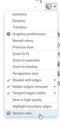
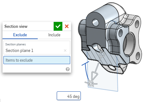
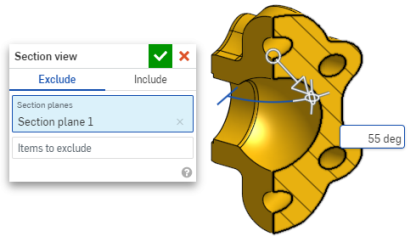
- Das Bauteil bzw. die Oberfläche wird an dem Punkt geschnitten, den Sie im 1. Schritt oben ausgewählt haben (zylindrische Fläche, konische Fläche, ebene Fläche, Ebene oder Verknüpfungsverbindung). Ein Manipulator erscheint an der zuletzt ausgewählten Position und ein Dialogfenster mit der Liste der Auswahlen wird geöffnet:
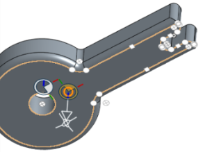
- Klicken Sie auf den offenen Kreis (die Kugel) des Manipulators und ziehen Sie ihn, um ihn zu positionieren. Er kann von jedem Ableitungspunkt des Bauteils oder der Baugruppe, einschließlich den Schwerpunkten von Zylindern, gefangen werden (die weißen Markierungen unten zeigen die Ableitungspunkte):
- Verwenden Sie den Manipulator, um die Tiefe und/oder den Winkel des Schnitts zu ändern.
- Ziehen Sie den Pfeil in die eine oder die andere Richtung, um die Tiefe zu ändern. Klicken Sie auf den Manipulator, um die Richtung der Ansicht umzukehren.
- Verwenden Sie die Winkelanzeigen, um einen Winkel zu ziehen.
- Verwenden Sie das numerische Feld im Grafikbereich, um die Tiefe oder den Winkel der Ansicht einzugeben.
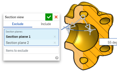
- Wenn Sie eine andere Schnittebene auswählen möchten, während das Dialogfenster geöffnet bleibt, klicken Sie auf die gewünschte Stelle für die neue Schnittebene. Daraufhin werden ein neuer Manipulator und eine neue Schnittebene angezeigt.
Um den auf die Schnittansichtsebene senkrecht liegenden Abschnitt anzuzeigen, verwenden Sie den Tastaturbefehl „N“. Oder rechtsklicken Sie und wählen Sie „Ansicht senkrecht zu“ im Kontextmenü aus.
- Um ein oder mehrere Bauteile (oder Oberflächen) aus der Schnittansicht auszuschließen, aktivieren Sie das Feld „Auszuschließende Elemente“ und treffen Sie dann Ihre Auswahl im Grafikbereich:
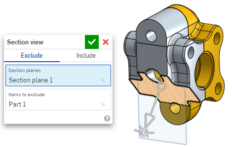
-
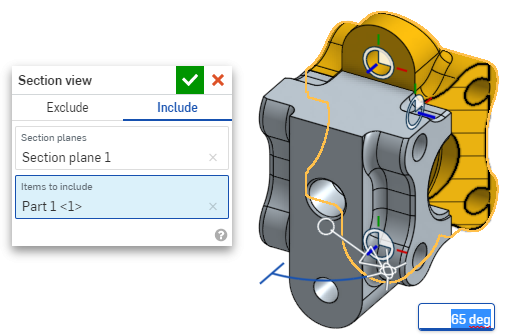
Um ein oder mehrere Bauteile (oder Oberflächen) in die Schnittansicht einzubeziehen, wählen Sie die Registerkarte „Einschließen“ und dann die Objekte aus, die in den Grafikbereich einbezogen werden sollen:
Um das Modell in der Schnittansicht zu verschieben, klicken Sie auf das Dialogfenster, um es zu schließen, und bearbeiten Sie dann das Modell wie gewünscht.
- Klicken Sie im Dialogfenster auf das Symbol „Standardebene auswählen“
 , um die Standard-Ebenenoptionen im Grafikbereich zu öffnen:
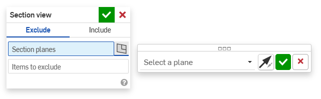
-
Wählen Sie eine Standardebene aus dem Dropdown-Menü aus. Das Dialogfenster „Schnittansicht“ wird entsprechend aktualisiert.
Klicken Sie optional auf das Symbol „Ebene umkehren“, um einfach zwischen der Vorder-/Rückseite oder der Oben/Unten- oder Rechts-/Linksansicht zu wechseln.
-
Klicken Sie auf das grüne Häkchen im Dialogfenster „Ebene auswählen“, um die Standard-Ebenenoptionen zu speichern und zu schließen, aber das Dialogfenster „Schnittansicht“ geöffnet zu lassen. Oder klicken Sie auf das grüne Häkchen im Dialogfenster „Schnittansicht“, um beide Dialogfenster zu speichern und zu schließen.
-
Wählen Sie im Menü „Kamera- und Rendering-Optionen“
oder im Kontextmenü die Option „Schnittansicht ausschalten“ aus, wenn Sie fertig sind.
Sie können auch die „Schnittansicht“ aktivieren, bevor Sie eine Auswahl treffen.
Wenn sich Bauteile überschneiden, werden diese in Rot dargestellt.
Wenn „Schnittansicht“ nicht ausgeschaltet ist und das Dialogfenster geschlossen wurde, öffnen Sie das Dialogfenster erneut, indem Sie auf die Schnittebene doppelklicken. Alternativ klicken Sie auf das Menü „Kamera und Rendering-Optionen“ ![]() oder rechtsklicken Sie auf das Bauteil oder die Baugruppe, um das Kontextmenü aufzurufen, und wählen Sie „Schnittansicht bearbeiten“ aus.
oder rechtsklicken Sie auf das Bauteil oder die Baugruppe, um das Kontextmenü aufzurufen, und wählen Sie „Schnittansicht bearbeiten“ aus.
Sie können die „Schnittansicht“ verwenden und die Ansicht als „Benannte Ansicht“ speichern.
Sie können das Mess-Tool auch in einer Schnittansicht für Flächen, Kanten und Eckpunkte verwenden. Siehe Mess-Tool für weitere Informationen.