 Transform Sketch
![]()
![]()
![]()
Transform adjusts a sketch's location, orientation, and scale.
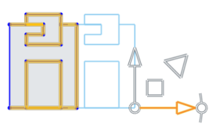
This video will show you how to use the Transform sketch tool. Transform adjusts the sketch's location and orientation. You can either select all the entities first, before you select the Transform tool, or you can select the Transform tool first, and then select the entities. So, in this case, let's select the Transform tool on the sketch toolbar, and then select the entities that you wish to move or orient. In order to move them you can use the arrows, and this will move them to a new location. When you're happy with the location, click the left mouse button, and the entities are moved. You can also move the entities upward, downward, left or right, in any direction.
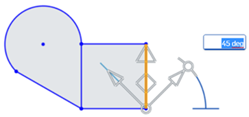
To change the angle of orientation for any of the entities, first, select the entities. Then select the Transform tool on the sketch toolbar, and then you can use the angle manipulator to adjust the angle of rotation, either negatively or positively. If you wish to enter the precise measurement, you can do so using your keyboard and then press the Enter key, and then press your left mouse button to accept the changes.
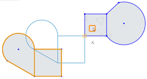
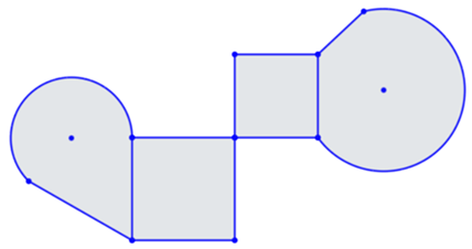
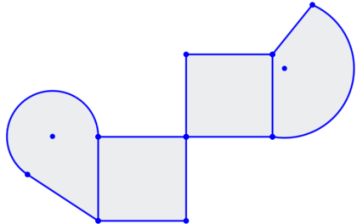
You can also use the Transform tool to connect two closed entity shapes together. First, click the Transform tool. Select the entities in the first closed shape. Place the manipulator ball's point to orient the snap point for the sketch — in this case the top right snap point of the square. Next, use the plane to drag the sketch ball point to the snap point on another sketch — in this case the lower left point of the square. Left-click with your mouse button to accept the change.
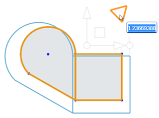
The transform tool can also be used to scale entities upward or downward. To do so, first select the transform tool on the sketch toolbar. Select the entities to which you want to scale, and then use the scale manipulator to drag upward to create a larger scale or downward to create a smaller scale. When you have the scale size that you wish, click the left mouse button to accept the changes.
Steps
-
Click
 .
.
- Select the sketch entities you want to move.
- Use the manipulator to drag and orient the sketch.
- Click in space when the sketch is placed and oriented as desired.
When rotating via the manipulator, an angle field activates. Enter an angle, press Enter, and click in space to set the angle:
Place the manipulator’s ball point to orient a snap point for the sketch:
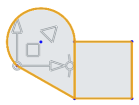
- Drag the ball point to a point on the sketch you wish to use as a snap point:
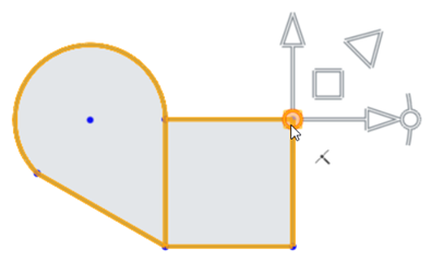
- Use the plane to drag the sketch ball point to the snap point on another sketch (in this case the lower-left point of the square):
- Click off the sketch to set the transform:
To scale the sketch entities click and drag the scale (triangle) manipulator outward or inward to scale up or down, respectively. Dragging activates the scale field. Enter a scale numerically, press Enter, and click in space to set the scale:
For more information, see Transforming sketches.
Tips
- Pre- and post-selection is supported; entities can be added and removed during the operation.
- Click off the sketch or press Enter to commit the transform and exit the operation. Press Esc to cancel the operation.
- In the case of no rotation or 180 degree rotation, internal constraints are unchanged.
- In the case of 90 degree or 270 degree rotation, horizontal and vertical constraints swap.
- In some cases, construction geometry may be added to maintain degrees of freedom.
- Directed dimensions are deleted, and may be replaced with construction geometry and minimum dimensions.
- Transform is also supported for images, text, DWG, and DXF.
Transform adjusts a sketch's location and orientation.
Steps
- With the sketch opened for editing, select the sketch entities you want to move.
-
In the Feature tool area, tap
 .
.
- Use the manipulator to drag and orient the sketch.
- Click in space when the sketch is placed and oriented as desired.
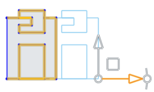
When rotating via the manipulator, an angle field activates. Tap in the numeric field, enter an angle, tap the checkmark, and tap in space to set the angle:
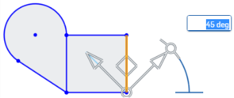
Place the manipulator’s ball point to orient a snap point for the sketch:
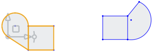
- Drag the ball point to a point on the sketch you wish to use as a snap point:
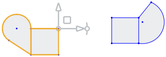
- Use the
plane
to drag the sketch ball point to the snap point on another sketch (in this case the lower-left point of the square):
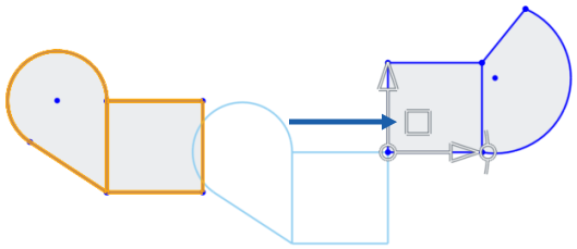
- Click off the sketch to set the transform:
Tips
- Pre- and post-selection is supported; entities may be added and removed during the operation.
- Tap off the sketch or tap the checkmark to commit the transform and exit the operation.
- In the case of no rotation or 180 degree rotation, internal constraints are unchanged.
- In the case of 90 degree or 270 degree rotation, horizontal and vertical constraints swap.
- In some cases, construction geometry may be added to maintain degrees of freedom.
- Directed dimensions are deleted, and may be replaced with construction geometry and minimum dimensions.
- Transform is also supported for images, text, DWG, and DXF.
Transform adjusts a sketch's location and orientation.
Steps
- With the sketch opened for editing, select the sketch entities you want to move.
-
In the Feature tool area, tap
 .
.
- Use the manipulator to drag and orient the sketch.
- Click in space when the sketch is placed and oriented as desired.

When rotating via the manipulator, an angle field activates. Tap in the numeric field, enter an angle, tap the checkmark, and tap in space to set the angle:

Place the manipulator’s ball point to orient a snap point for the sketch:

- Drag the ball point to a point on the sketch you wish to use as a snap point:

- Use the
plane
to drag the sketch ball point to the snap point on another sketch (in this case the lower-left point of the square):

- Click off the sketch to set the transform:

Tips
- Pre- and post-selection is supported; entities may be added and removed during the operation.
- Tap off the sketch or tap the checkmark to commit the transform and exit the operation.
- In the case of no rotation or 180 degree rotation, internal constraints are unchanged.
- In the case of 90 degree or 270 degree rotation, horizontal and vertical constraints swap.
- In some cases, construction geometry may be added to maintain degrees of freedom.
- Directed dimensions are deleted, and may be replaced with construction geometry and minimum dimensions.
- Transform is also supported for images, text, DWG, and DXF.