 Dimension
![]()
![]()
![]()
Add horizontal, vertical, shortest distance, angular, diametrical, arc length, or radial dimensions to sketch geometry, as well as between sketch geometry and planes. You are able to specify dimensions as driven (reference) or driving.
Shortcut: d
You have the ability to use the Measure tool to measure anything in the graphics area.
Some tools allow you to dimension as you sketch.
You can also use the Show dimensions command in the context menu (RMB) of a sketch to view existing dimensions.
Dimensions are a robust way to define sketch entities. Two methods are available for adding dimensions to a sketch. The first method involves adding dimensions while creating the sketch, while the second method involves creating sketch geometry first and then adding dimensions.
To add dimensions while sketching, type in a number and hit enter after sketching the geometry. For example, place a line. After selecting the second endpoint, a white box appears with the length of the line. Enter a value and press Enter to assign a dimension. This method applies to nearly all sketch tools.
When defining geometry that involves two dimensions, like a rectangle, start by entering the horizontal dimension and then press Enter. The input will automatically switch to the vertical dimension.
The second method for adding dimensions is to add them after the sketch geometry is finished. Select the dimension tool or use the shortcut D. Left-click on the entity or entities to apply the dimension. Move the cursor and left-click to place the dimension. Enter the value for the dimension and press enter. The sketch automatically scales to match the first dimension placed.
Onshape’s sketch dimension intuitively responds to the type of entity selected. This makes dimensioning to the outside or inside of an arc or circle seamless. Left-click close to the outside of the arc or circle to dimension to the outside. Left-click close to the inside of the arc or circle to dimension to the inside.Following the same intuitive theme, the dimension tool automatically places an angle dimension when dimensioning two non-parallel lines.
To edit a dimension, double-click the dimension in the graphics. Type a new value and press Enter to accept. Select the dimension from the graphics area to delete a dimension and press Delete on the keyboard. You can also use Dimension to display a value driven by other dimensions and relationships. Driven dimensions appear as gray in the sketch, whereas driving dimensions are black. Onshape automatically toggles new dimensions to driven if their placement will over-define a sketch. Manually toggle a dimension’s driving status in the right-click menu.
-
Click
 or press the d key.
- Select the entity (or entities between which) to dimension and the location of the dimension.
The selected entity or entities are highlighted (browser only), and the dialog opens on the placement of the dimension.
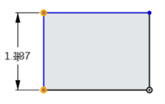
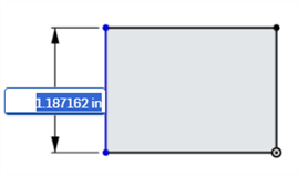
- Enter a value and press Enter to accept the value. You can also use a variable for a dimension, simply enter "=#" and the variable name, as in: =#d.
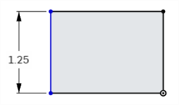
You can enter negative values for dimensions (length, linear distance, and angles) to flip the direction of the entity.
The image below shows a positive dimension; notice the position of the rectangle relative to the bottom horizontal line:
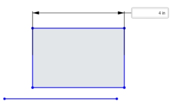
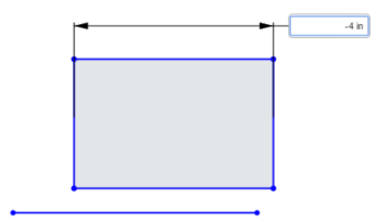
The following image shows a negative dimension value being typed into the active field:
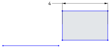
When the value is accepted, the rectangle flips direction:
-
You can use expressions and trigonometric functions in numeric fields in Part Studios.
-
Delete a dimension by selecting it and pressing the Delete key, or select it and select Delete from the context menu.
-
To edit a placed dimension, double-click the value to activate the field, then enter the new value. Press Enter to accept the change.
-
Except for Diameter and radius dimensions, when a new dimension value is entered, both geometric selections being dimensioned are translated by half the new input value, so that both geometric selections are translated equally. For example, when dimensioning a single line, each endpoint is translated by half the dimension value, so that both endpoints are translated equally.
-
Constrained geometry may not translate. See Working with constraints.
Single line distance
- Click the Dimension tool (
 ).
). - Click the line.
- Drag to position the linear distance dimension.
- Click to simultaneously place the dimension and open its numeric value field.
-
Optionally, enter a new dimension value.
-
Press Enter to accept the dimension value.

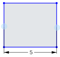
This is the method used to dimension length or height:
Distance between 2 lines
- Click the Dimension tool (
 ).
). - Click the first line
- Click the second line
- Drag to position the linear distance dimension
- Click to simultaneously place the dimension and open its numeric value field.
-
Optionally, enter a new dimension value.
-
Press Enter to accept the dimension value.

When dimensioning between two lines, this implies parallelism without a visual parallel constraint.
-
Click the Dimension tool (
 ).
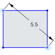
). - Click the first corner point
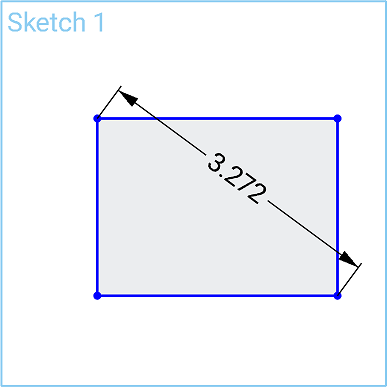
- Click the second corner point, diagonal to the first.
- Drag at an angle to position the diagonal distance dimension
- Click to simultaneously place the dimension and open its numeric value field.
-
Optionally, enter a new dimension value.
-
Press Enter to accept the dimension value.
- Click the Dimension tool (
 ).
). - Click the edge of the circle.
- Drag into or away from the circle to position the diameter dimension.
- Click to simultaneously place the dimension and open its numeric value field.
-
Optionally, enter a new dimension value.
-
Press Enter to accept the dimension value.
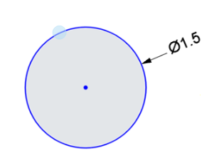
-
Click the Dimension tool (
 ).
). - Click the first line.
- Click the second line, at an angle to the first.
- Drag into or out of the angle to position the angle dimension.
You can also drag the dimension to the quadrant for which you want to define the angle:
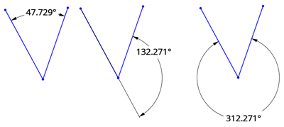
- Click to simultaneously place the dimension and open its numeric value field.
-
Optionally, enter a new dimension value.
-
Press Enter to accept the dimension value.
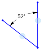
Direct distance
This dimensions the shortest distance between 2 points.
-
Click the Dimension tool (
 ).
). - Click the endpoint of the first line
- Click the endpoint of the second line.
- Drag at an angle to position the direct distance dimension.
- Click to simultaneously place the dimension and open its numeric value field.
-
Optionally, enter a new dimension value.
-
Press Enter to accept the dimension value.
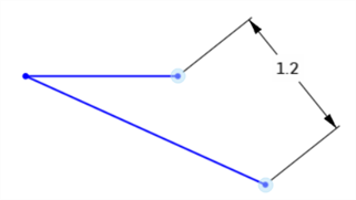
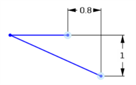
Linear distance
This dimensions the linear distance between 2 points.
-
Click the Dimension tool (
 ).
). - Click the endpoint of the first line
- Click the endpoint of the second line.
- Drag straight up/down or left/right to position the linear distance dimension.
- Click to simultaneously place the dimension and open its numeric value field.
-
Optionally, enter a new dimension value.
-
Press Enter to accept the dimension value.
-
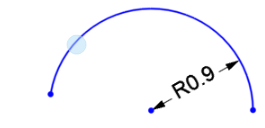
Click the Dimension tool (
 ).
). - Click the arc.
- Drag into or away from the arc to position the radius dimension.
- Click to simultaneously place the dimension and open its numeric value field.
-
Optionally, enter a new dimension value.
-
Press Enter to accept the dimension value.
-
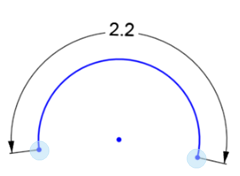
Click the Dimension tool (
 ).
). -
Click the arc’s first endpoint.
-
Click the arc’s second endpoint.
-
Click the arc.
-
Drag to position the arc length dimension.
-
Click to simultaneously place the dimension and open its numeric value field.
-
Optionally, enter a new dimension value.
-
Press enter to accept the dimension value.
This dimensions the distance between 2 points on a spline or a spline point and any other sketch point.
-
Click the Dimension tool (
 ).
).
-
Click the first spline point.
-
Click the second spline point (or any other sketch point).
-
Drag to position the distance dimension.
-
Click to simultaneously place the dimension and open its numeric value field.
-
Optionally, enter a new dimension value.
-
Press enter to accept the dimension value.
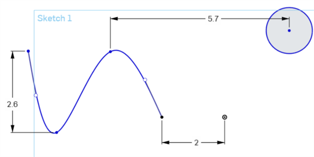
You can also get the direct distance between two points on a spline or a spline point and any other sketch point if you drag the cursor away at an angle to position the direct distance dimension. See Direct distance.
This dimensions the distance between a plane and any other sketch point.
-
Click the Dimension tool (
 ).
).
-
Click the sketch point.
-
Click the plane.
-
Drag to position the distance dimension.
-
Click to simultaneously place the dimension and open its numeric value field.
-
Optionally, enter a new dimension value.
If a new dimension value is entered, the sketch geometry moves while the plane remains in place.
-
Press enter to accept the dimension value.
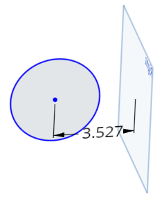
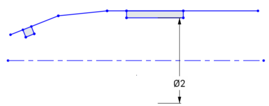
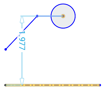
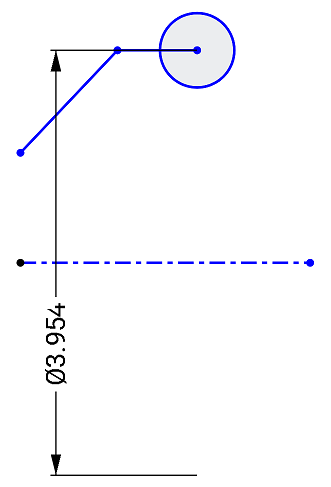
Create a centerline dimension between a circle, point, or non-construction line to a construction line; for instance, to dimension a part for a revolve operation. Start a distance dimension between one of these sketch entities and then move the mouse to the opposite side of the construction line. Moving the mouse across the construction line toggles the state between distance and centerline dimensions:
-
Click the Dimension tool (
 ).
).
-
Click the circle or sketch point.
-
Click the Construction line. This results in a distance dimension between the 2 lines:

- Drag to the opposite side of the construction line to simultaneously toggle the state to a centerline dimension and position the centerline dimension.
- Click to simultaneously place the dimension and open its numeric value field.
-
Optionally, enter a new dimension value.
-
Press Enter to accept the dimension value.
Driven dimensions are useful for maintaining design intent, such as keeping a clearance or wall thickness above a certain value.
- Dimensions are driving by default. Right-click on a dimension value to select "Driving/Driven" from the context menu.
- Driving dimensions appear black and can be edited.
- Driven dimensions appear light gray and cannot be edited (Toggle it to 'driving' and then edit, if necessary.)
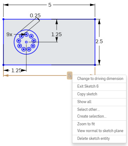
- When a dimension added to a sketch over-defines the sketch, the dimension is automatically made 'driven'.
- You are able to add driven dimensions anywhere a driving dimension can be added.
- Driven dimensions reflect the value of the implied dimension; it does not change geometry.
- When a dimension is switched from driven to driving, it changes the geometry; if changing a driven dimension to driving causes the sketch to be over-constrained, red indicators appear as usual.
Onshape allows users to enter negative values for some dimensions but not all. See below for which dimensions accept negative values.
Onshape allows negative values for:- Distance dimension
- Angle dimension
- Line length
- Spline dimension
- Arc dimension
- Radius or diameter dimension
- Tap Dimension tool.
- Select the entity (or entities) between which to dimension, and the location of the dimension.
The dialog opens on the placement of the dimension.
- Enter a value and select the checkmark to accept the value.
- Tap to select a corner point.
- Tap to select the opposite corner point.
- The current value appears, tap on it to open the number pad.
- Use number pad to enter a dimension.
- Tap to select a vertical or horizontal line.
- The current value of the length or height appears, tap on it to open the number pad.
- Use the number pad to enter a dimension.
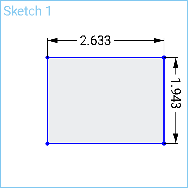
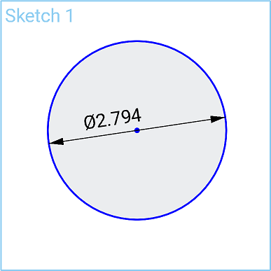
- Tap to select the edge of circle.
- The current value appears, tap on it to open the number pad.
- Use the number pad to enter a dimension.
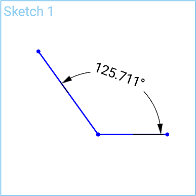
- Tap to select a line.
- Tap to select another line.
- The current value of the angle between the two lines appears, tap on it to open the number pad.
- Use the number pad to enter a dimension.
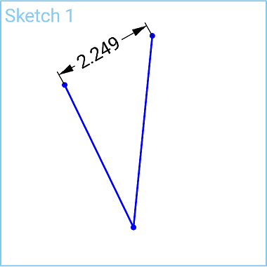
Linear distance / direct distance
- Tap to select a point.
- Tap to select another point.
- The current value appears, tap on it to open the number pad.
- Use the number pad to enter a dimension.
- Tap the edge of an arc to select it.
- The current value of the radius appears, tap on it to open the number pad.
- Use the number pad to enter a dimension.
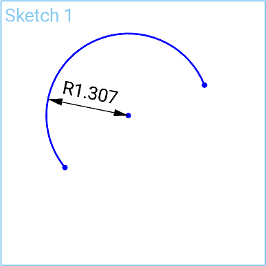
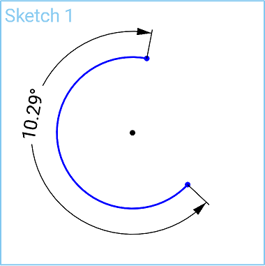
Arc length
- Tap to select both points of an arc.
- Tap on the curve of the arc to select it.
- The arc length value appears, tap on it to open the number pad.
- Use the number pad to enter a dimension.
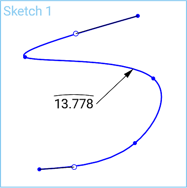
Spline curve length
- Tap a spline to select it.
- The curve length value appears, tap on it to open the number pad.
- Use the number pad to enter a dimension.
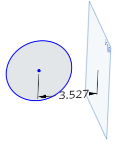
- Tap to select a point.
- Tap to select a plane.
- The current value appears, tap on it to open the number pad.
- Use the number pad to enter a dimension.
Create a centerline dimension between a circle, point, or non-construction line to a construction line; for instance, to dimension a part for a revolve operation.
- Tap to select the point to dimension.
- Tap to select the construction line to create as the centerline.
A dimension is set between the point and the construction line.
- Touch and drag the dimension across the construction line.
Once the dimension crosses the construction line, the construction line becomes the centerline and the dimension adjusts accordingly.
- Driven dimensions are useful for maintaining design intent, such as keeping a clearance or wall thickness above a certain value.
- Dimensions are driving by default. Tap to select a dimension, then two-finger tap to bring up the context menu. In the context menu you can tap to Toggle Driven/Driving dimensions.
- Driving dimensions appear black and can be edited.
- Driven dimensions appear light gray and are not able to be edited (toggle a driven dimension to driving and then edit, if necessary).
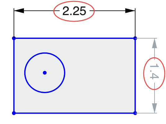
- When a dimension added to a sketch over-defines the sketch, the dimension is automatically made 'driven'.
- You are able to add driven dimensions anywhere a driving dimension can be added.
- Driven dimensions reflect the value of the implied dimensions; it does not change geometry.
- When a dimension is switched from driven to driving, it changes the geometry; if changing a driven dimension to driving causes the sketch to be over-constrained, red indicators appear as usual.
Onshape allows users to enter negative values for some dimensions but not all. See below for which dimensions accept negative values.
iOS allows negative values for:
- Distance dimension
- Angle dimension
- Line length
iOS does not allow negative values for:
- Arc dimension
- Spline dimension
- Radius or Diameter dimension
- Tap Dimension tool.
- Select the entity (or entities) between which to dimension, and the location of the dimension.
The dialog opens on the placement of the dimension.
- Enter a value and select the checkmark to accept the value.
- Tap to select a corner point.
- Tap to select the opposite corner point.
- The current value appears, tap on it to open the number pad.
- Use number pad to enter a dimension.

- Tap to select a vertical or horizontal line.
- The current value of the length or height appears, tap on it to open the number pad.
- Use the number pad to enter a dimension.

- Tap to select the edge of circle.
- The current value appears, tap on it to open the number pad.
- Use the number pad to enter a dimension.

- Tap to select a line.
- Tap to select another line.
- The current value of the angle between the two lines appears, tap on it to open the number pad.
- Use the number pad to enter a dimension.

Linear distance / direct distance
- Tap to select a point.
- Tap to select another point.
- The current value appears, tap on it to open the number pad.
- Use the number pad to enter a dimension.

- Tap the edge of an arc to select it.
- The current value of the radius appears, tap on it to open the number pad.
- Use the number pad to enter a dimension.

Arc length
- Tap to select both points of an arc.
- Tap on the curve of the arc to select it.
- The arc length value appears, tap on it to open the number pad.
- Use the number pad to enter a dimension.

Spline curve length
- Tap a spline to select it.
- The curve length value appears, tap on it to open the number pad.
- Use the number pad to enter a dimension.

- Tap to select a point.
- Tap to select a plane.
- The current value appears, tap on it to open the number pad.
- Use the number pad to enter a dimension.

Create a centerline dimension between a circle, point, or non-construction line to a construction line; for instance, to dimension a part for a revolve operation.
- Tap to select the point to dimension.
- Tap to select the construction line to create as the centerline.
A dimension is set between the point and the construction line.
- Touch and drag the dimension across the construction line.
Once the dimension crosses the construction line, the construction line becomes the centerline and the dimension adjusts accordingly.


- Driven dimensions are useful for maintaining design intent, such as keeping a clearance or wall thickness above a certain value.
- Dimensions are driving by default. Double tap a dimension to open the Number pad, then tap the Driven/Driving button to switch the dimension type. The button says what type of dimension you have selected. Tap the button to switch to the opposite type of dimension.
- Driving dimensions appear black and can be edited.
- Driven dimensions appear light gray and are able to be edited (toggle a driven dimension to driving and then edit, if necessary).

- When a dimension added to a sketch over-defines the sketch, the dimension is automatically made 'driven'.
- You are able to add driven dimensions anywhere a driving dimension can be added.
- Driven dimensions reflect the value of the implied dimensions; it does not change geometry.
- When a dimension is switched from driven to driving, it changes the geometry; if changing a driven dimension to driving causes the sketch to be over-constrained, red indicators appear as usual.
Onshape allows users to enter negative values for some dimensions but not all. See below for which dimensions accept negative values.
Android allows negative values for:
- Distance dimension
- Angle dimension
- Line length
- Spline dimension
Android does not allow negative values for:
- Arc dimension
- Radius or Diameter dimension