 Sheet Metal Model
![]()
![]()
![]()
Create sheet metal parts by converting existing parts, extruding sketch curves (including arcs and splines to create rolled sheet metal), or thickening faces or sketches.
Add to sheet metal parts by converting existing parts, extruding sketch curves (including arcs and splines to create rolled sheet metal), or thickening faces or sketches. All operations on active sheet metal models are automatically represented as a flat pattern, and joints and bends are listed in a sheet metal table. The folded, flat, and table views are available and updated simultaneously and in real time. Sheet metal models may consist of multiple parts, and multiple sheet metal models may be active simultaneously.
The Sheet metal model tool activates a sheet metal feature. Consequently, features affecting that sheet metal model affect it as a piece of sheet metal. The Finish sheet metal tool deactivates the sheet metal feature, allowing features to affect the model as a 3D model and not as sheet metal.
For example, when the sheet metal model is active, any features piercing the sheet metal are perpendicular to the walls whereas when deactivated, any feature piercing the walls are subject to the angle between the feature and the wall.
You are also able to use the additional sheet metal tools to create flanges, define and modify joints, convert bends to rips and vice versa, define corner parameters, as well as view the sheet metal as a 3D part and in flattened view simultaneously. Onshape also provides a sheet metal table listing bends and rips, where you are able to edit corner radii and joint types as well as create a drawing of the sheet metal part.
This video explains how to create a sheet metal model using the Convert operation.
Click the Sheet metal model feature tool on the Part Studio toolbar. By default, the sheet metal operation type is Convert. Leave this selected.
Select the parts and surfaces to convert in the graphics area. Select the Faces to exclude from the operation. Select the edges to define bends; edges not selected are made into rips. Arcs or splines not selected in the Edges or cylinders to bend field become tangent joints, not bends.
Check Include bends to include the bend within the clearance value.
Check Keep input parts to keep the originally selected parts (enclosed by the sheet metal).
Click the General dropdown and enter the Thickness for the sheet metal. Click the arrow to reverse the thickness direction. Enter the Bend radius to adjust the inside radius of the bends created. Check Flip direction up to reverse the orientation of the sheet metal model. This is useful when defining whether bends are up or down, relative to the model.
Use the Material and Relief dropdown options to further refine the sheet metal model.
Click the checkmark to accept the new sheet metal model.
Create a sheet metal model by enclosing existing parts:
- While in a Part Studio, click
 .
.
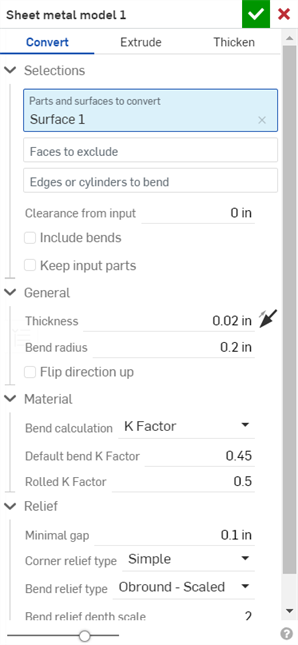
- Select the type of sheet metal operation: Convert
- Select the parts to enclose.
- Select the faces to exclude from the operation.
- Select the edges to define bends; edges not selected are made into rips.
Arcs or splines not selected in the "Edges or cylinders to bend" field become tangent joints, not bends. See the example below.
- Specify applicable options:
- Clearance from input - The relative offset between the sheet metal and the part selected to be enclosed by the sheet metal
- Include bends - Check this to include the bend within the clearance value
- Keep input parts - Keep the selected parts (enclosed by the sheet metal) or not
- Thickness - The thickness of the sheet metal
- Bend radius - The inside radius of the bends created
- Flip direction up - Reverses the orientation of the sheet metal model and flat view. This is useful when defining whether bends are up or down, relative to the model.
- Bend calculation - Determines how the bends are calculated. Options are:
- K Factor (default) - Uses the ratio of the neutral axis to the material thickness.
- Bend allowance - Uses the length of the neutral line arc between the tangent points of a bend.
- Bend deduction - Uses the difference between the sum of the flange lengths (from the edge to the apex) and the initial flat length.
The Bend calculation selected here is used as a column in the sheet metal table. Each bend may be customized and directly edited from the table. See Sheet metal table and flat view for more information.
- Default bend K Factor - The fraction of material thickness on which the neutral axis lies on a bend. (Default is 0.45.)
- Rolled K Factor - The fraction of material thickness on which the neutral axis lies on a section of rolled wall. (Default is 0.5.)
- Minimal gap - The smallest gap between the sheet metal edges defining a rip
- Corner relief type
-
- Square - Sized
Flat view:
 3D view:

- Rectangle - Scaled
Flat view:
 3D view:

- Round - Sized
Flat view:
 3D view:

- Round - Scaled
Flat view:
 3D view:

- Closed
Flat view:
 3D view:

- Simple
Flat view:
 3D view:

- Square - Sized
- Corner relief scale - The scale of the corner opening (for Scaled openings), a value between 1.00 and 2.00.
- Corner relief width - The measurement of the width of the corner opening (for Sized openings), in default units or specified units.
- Bend relief type
- The shape of the bend relief:
- Rectangle - Scaled

- Obround - Scaled

- Tear

- Bend relief depth scale
- A value between 1.00 and 5.00. Once you enter a value it becomes the default across all documents.
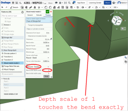
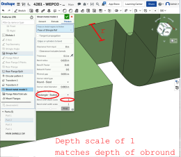
A value of 1 results in an obround bend relief perfectly touching the bend and a rectangular bend relief matches the depth of the obround:
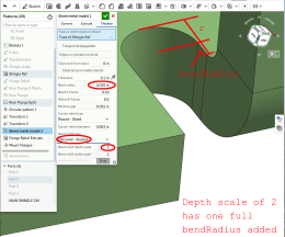
Any value past 1 adds depth via the formula: ((depth scale -1) * bendRadius):
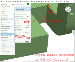
- Bend relief width scale - A value between 0.0625 and 2.00. The width of the bend relief is calculated via the formula: thickness * width scale. Once you enter a value it becomes the default across all documents.
-
Click
 to accept the feature; the Sheet metal model is listed in the Feature list.
- Apply any other specific sheet metal features now.
- Click
Finish sheet metal model
 if you want to continue to add non-sheet metal features to your part.

You are able to create sheet metal from conical parts that revolve around a single axis.
This video explains how to create a sheet metal model using the Extrude operation.
Click the Sheet metal model feature tool on the Part Studio toolbar. Select the Extrude sheet metal model operation. Select the Sketch curves to extrude in the graphics area. Optionally, select Arcs to extrude as bends. This results in any selected arc being made into a bend (instead of a tangent joint) and lists it in the bend table with its radius grayed out. Since the arc has a radius in the sketch, you are unable to edit it in the bend table. Select the End type: Blind, Up to next, Up to face, Up to part, or Up to vertex. Click the arrow to extrude in the opposite direction.
Enter the depth numerically in the dialog or use the manipulator in the graphics area.
Check Symmetric (available only for Blind and Through all end types) to extrude in both directions of the sketch plane.
Alternatively, instead of using the Symmetric option, check Second end position to specify the opposing end position so its depth is different from the primary depth.
In the General dropdown enter the Thickness for the sheet metal. Click the arrow to reverse the thickness direction. Enter the Bend radius to adjust the inside radius of the bends created. Check Flip direction up to reverse the orientation of the sheet metal model. This is useful when defining whether bends are up or down, relative to the model.
Use the Material and Relief dropdown options to further refine the sheet metal model.
Click the checkmark to accept the new sheet metal model.
Create a sheet metal model by extruding sketch curves:
- While in a Part Studio, click
 .
.
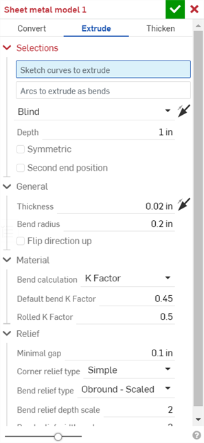
- Select the sheet metal operation Extrude.
- Select the sketch curves to extrude.
- Select the End type: Blind, Up to next, Up to face, Up to part, Up to vertex.
- Symmetric - Select this option, available for Blind end types only, to a specified total distance, half the distance in both directions about the sketch plane.
- Drag or set the depth.
- Set the thickness of the sheet metal.
- Set the inside radius of the bends.
- Check Flip direction up if you wish to reverse the orientation of the sheet metal model and flat view.
- Select the Bend calculation to determine how the bends are calculated. Options are:
- K Factor (default) - Uses the ratio of the neutral axis to the material thickness.
- Bend allowance - Uses the length of the neutral line arc between the tangent points of a bend.
- Bend deduction - Uses the difference between the sum of the flange lengths (from the edge to the apex) and the initial flat length.
The Bend calculation selected here is used as a column in the sheet metal table. Each bend may be customized and directly edited from the table. See Sheet metal table and flat view for more information.
-
Specify the K Factor - The fraction of material thickness on which the neutral axis lies.
- Set Minimal gap - The smallest gap between sheet metal edges.
- Corner relief type:
- Square - Sized
Flat view:
 3D view:

- Rectangle - Scaled
Flat view:
 3D view:

- Round - Sized
Flat view:
 3D view:

- Round - Scaled
Flat view:
 3D view:

- Closed
Flat view:
 3D view:

- Simple
Flat view:
 3D view:

- Square - Sized
- Corner relief scale - The scale of the corner opening (for Scaled corners); a value between 1.00 and 2.00.
- Bend relief type
- The shape of the bend relief:
- Rectangle - Scaled:

- Obround - Scaled:

- Tear:

- Bend relief depth scale - Between 1.00 and 2.00
- Bend relief width scale - A value between 0.0625 and 2.00
-
Click
 to accept the feature; the Sheet metal model is listed in the Feature list.
- Apply any other specific sheet metal features now. See note below.
-
Click
Finish sheet metal model
 if you want to continue to add non-sheet metal features to your part.
-
Click
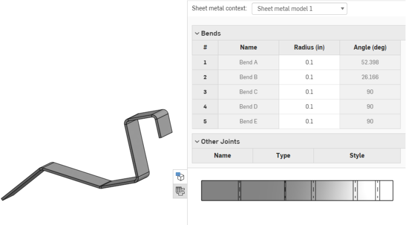
 to close the Sheet metal feature; the Finish sheet metal model feature is listed in the Feature list, has a flat pattern and a sheet metal table listing the bends and joints:
When using an arc or spline to define a rolled wall, the sheet metal table and the flat pattern is a bit different. No bend is listed for the rolled wall, instead a tangent joint is listed in the table:
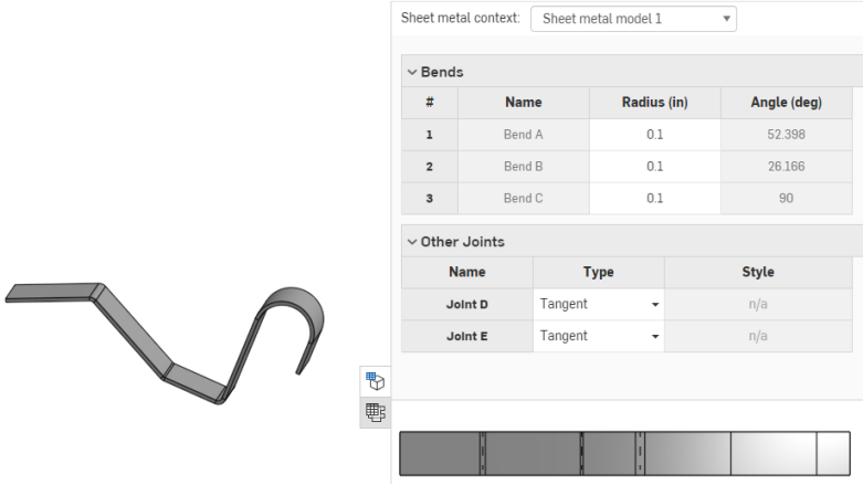
Similarly, no bend lines are shown in the flat pattern, since no bends are made.
You are able to create sheet metal from conical parts that revolve around a single axis.
You may decide to extrude an arc as a bend, however, by selecting the arc while the "Arcs to extrude as bends" field is active, as shown below:
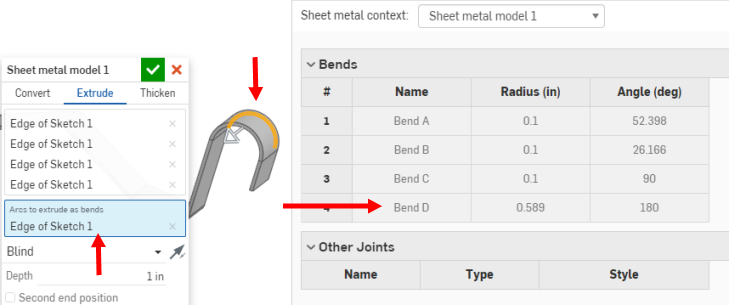
This results in the selected arc (or arcs) being made into bends (instead of tangent joints) and listed in the bend table with their radius grayed out. Since the arc has a radius in the sketch, you are unable to edit it in the bend table.
This video explains how to create a sheet metal model using the Thicken operation.
Click the Sheet metal model feature tool on the Part Studio toolbar. Select the Thicken sheet metal model operation. Select the Faces or sketch regions to thicken in the graphics area.
Check Tangent propagation to continue thickening along tangential edges.
Select Edges or cylinders to bend; edges not selected are made into rips or, in the case of arcs and splines, are made into tangent joints.
Enter a Clearance from input value: The relative offset between the sheet metal and the part selected to be enclosed by the sheet metal.
Check Include bends to include the clearance for bends.
In the General dropdown enter the Thickness for the sheet metal. Click the arrow to reverse the thickness direction. Enter the Bend radius to adjust the inside radius of the bends created. Check Flip direction up to reverse the orientation of the sheet metal model. This is useful when defining whether bends are up or down, relative to the model.
Use the Material and Relief dropdown options to further refine the sheet metal model.
Click the checkmark to accept the new sheet metal model.
Create a sheet metal model by thickening faces, surfaces or sketch regions:
- While in a Part Studio, click
 .
.
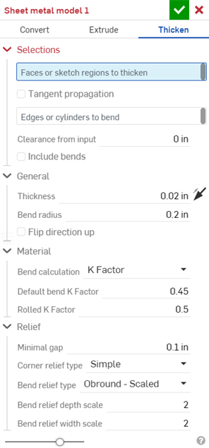
- Select the type of sheet metal operation: Thicken
- Select sketch regions, planar surfaces or faces of a part.
- Select the edges to create bends; edges not selected are made into rips or, in the case of arcs and splines, are made into tangent joints.
- Specify applicable options:
- Clearance from input - The relative offset between the sheet metal and the part selected to be enclosed by the sheet metal
- Clearance includes bends - Check to include the clearance for bends
- Thickness - The thickness of the sheet metal
- Bend radius - The inside radius of the bends created
- Flip direction up - Reverses the orientation of the sheet metal model and flat view. This is useful when defining whether bends are up or down, relative to the model.
- Bend calculation - Determines how the bends are calculated. Options are:
- K Factor (default) - Uses the ratio of the neutral axis to the material thickness.
- Bend allowance - Uses the length of the neutral line arc between the tangent points of a bend.
- Bend deduction - Uses the difference between the sum of the flange lengths (from the edge to the apex) and the initial flat length.
The Bend calculation selected here is used as a column in the sheet metal table. Each bend may be customized and directly edited from the table. See Sheet metal table and flat view for more information.
- Default bend K Factor - The fraction of material thickness on which the neutral axis lies. (Default is 0.45.)
Rolled K Factor - The fraction of material thickness on which the neutral axis lies on a section of rolled wall. (Default is 0.5.)
- Minimal gap - The smallest gap between sheet metal edges
- Corner relief type
- The shape of the corner relief:
- Square - Sized
Flat view:
 3D view:

- Rectangle - Scaled
Flat view:
 3D view:

- Round - Sized
Flat view:
 3D view:

- Round - Scaled
Flat view:
 3D view:

- Closed
Flat view:
 3D view:

- Simple
Flat view:
 3D view:

- Square - Sized
- Corner relief scale - The scale of the corner opening (for Scaled corners); a value between 1.00 and 2.00.
- Bend relief type:
- Rectangle:

- Obround:

- Tear:

- Bend relief depth scale - Between 1.00 and 2.00.
- Bend relief width scale - Between 0.0625 and 2.00.
-
Click
 to accept the feature; the Sheet metal model is listed in the Feature list.
- Apply any other specific sheet metal features now. See note below.
-
Click
Finish sheet metal model
 if you want to continue to add non-sheet metal features to your part.
-
Click
 to close the Sheet metal model feature; the Finish sheet metal model feature is listed in the Feature list.

When using an arc or spline to define a rolled wall, the sheet metal table and the flat pattern is a bit different. No bend is listed for the rolled wall, instead a tangent joint is listed in the table:

Similarly, no bend lines are shown in the flat pattern, since no bends are made.
You are able to decide to thicken an arc as a bend, however, by selecting the arc while the "Arcs to extrude as bends" field is active, as shown below:
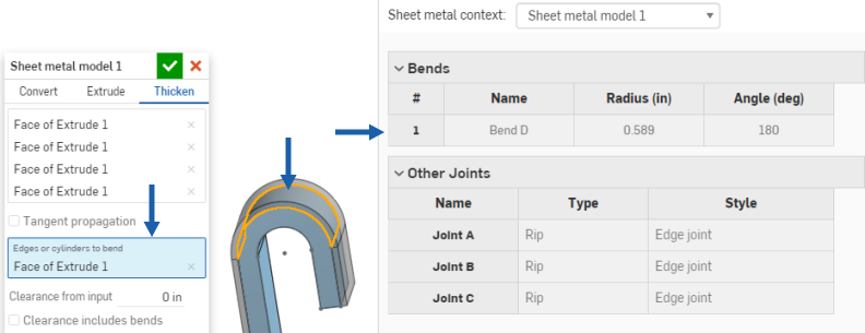
This results in the selected arc (or arcs) being made into bends (instead of tangent joints) and listed in the bend table with their radius grayed out. Since the arc has a radius in the sketch, you are unable to edit it in the bend table.
Only a subset of available features can be added to active sheet metal models (Extrude > Remove, Move face, Boolean, and Hole for example). All features are represented in the feature list, the model in the graphics area, the sheet metal table, and the flat pattern. For example, you are able to Extrude > Remove a sketch to create an opening in an active sheet metal model. The resulting opening’s sides are always perpendicular to the wall it pierces.
Other Extrude options that modify the model such as Add or Intersect are not allowed until the model is deactivated using the Finish sheet metal model tool.
Keep in mind that subsequent features modifying a deactivated sheet metal model act on the part as they would any non-sheet metal part, and do not affect the flat pattern or table values.
Use Fillet and Chamfer to soften sheet metal edges, if necessary. Be aware that selecting a sheet metal edge must be done at the very corner and not an adjacent edge. Note that advanced Fillet and Chamfer features (conic fillet for example) are not available on sheet metal at this time.
Onshape retains the original construction edge despite a fillet or chamfer and uses that construction edge for future features. For example, creating a flange on a filleted edge ignores the fillet and creates the flange along the original edge. You may use the Move face tool to move the edge of the flange back to the edge of the fillet if desired:
Fillet a corner:
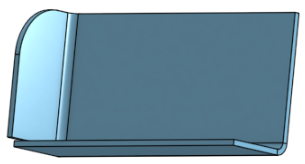
Create a flange:
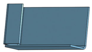
Use Move face to move the edge of the flange:
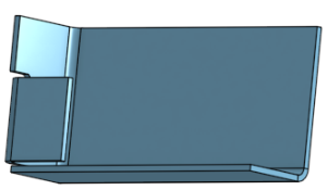
Re-fillet the corner:
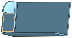
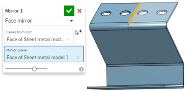
You have the ability to pattern sheet metal faces and flanges using the Face parameter of the patterning tools (Linear pattern, Circular pattern, and Curve pattern) as well as mirroring sheet metal faces and flanges. The tools function normally, just make sure to select "Face" as the Pattern type, or to select a face when mirroring:
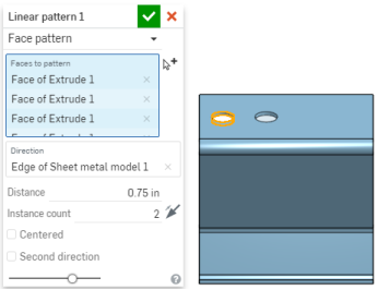
When a sheet metal model is active (in the process of being created or edited), additional tools are available:
-
 Flange - Create a wall for each edge selected, connected to the selected edge with a bend.
 -
 Hem - Create a hem for each edge/face selected, on an existing sheet metal part.
 -
 Tab - Add a tab to a sheet metal flange.
 -
 Bend - Bend a sheet metal model along a reference line, with additional bend control options.
 -
 Form - Create form features on existing sheet metal models. Forms can be selected from the current document, other documents, or a predefined library of sheet metal forms.
 -
 Make joint - Convert the intersection of two walls into a joint feature, either a bend (walls joined by cylindrical geometry) or a rip (small gap between two walls).
 -
 Corner - Modify a corner type and relief scale.
 -
 Bend relief - Modify a bend relief (the small cut made where the bend end meets the free edge), depth and relief width.
 -
 Modify joint - Make changes to an existing joint, such as converting a bend to a rip. Currently available through the flat view table.
 -
 Corner break - Break the corner on existing sheet metal parts by applying a fillet or chamfer. Select a corner edge or vertex and specify corner break type and distance. It is recommended to use this feature after all flanges and joints of the Sheet metal model are finalized.
 -
 Sheet metal table and flat view - Open and close the Rip/Bend tables and the visualization of the sheet metal model flat pattern. Use this table to convert rips to bends and vice versa.
 -
 Finish sheet metal model - Closes (deactivates) the Sheet metal model; creates a feature in the Feature list.
Create a sheet metal model by enclosing existing parts:
-
While in a Part Studio, tap
 .
.
- Select the type of sheet metal operation: Convert
- Select the parts to enclose.
- Select the faces to exclude from the operation.
- Select the edges to define bends; edges not selected are made into rips.
Arcs or splines not selected in the Edges or cylinders to bend field become tangent joints, not bends.
- Specify applicable options:
- Clearance from input - The relative offset between the sheet metal and the part selected to be enclosed by the sheet metal
- Clearance includes bends - Check this to include the bend within the clearance value
- Keep input parts - Keep the selected parts (enclosed by the sheet metal) or not
- Thickness - The thickness of the sheet metal
- Bend radius - The inside radius of the bends created
- Flip direction up - Reverses the orientation of the sheet metal model and flat view. This is useful when defining whether bends are up or down, relative to the model.
- Bend calculation - Determines how the bends are calculated. Options are:
- K Factor (default) - Uses the ratio of the neutral axis to the material thickness.
- Bend allowance - Uses the length of the neutral line arc between the tangent points of a bend.
- Bend deduction - Uses the difference between the sum of the flange lengths (from the edge to the apex) and the initial flat length.
The Bend calculation selected here is used as a column in the sheet metal table. Each bend may be customized and directly edited from the table. See Sheet metal table and flat view for more information.
- Default bend K Factor - The fraction of material thickness on which the neutral axis lies on a bend. (Default is 0.45.)
- Rolled K Factor - The fraction of material thickness on which the neutral axis lies on a section of rolled wall. (Default is 0.5.)
- Minimal gap - The smallest gap between the sheet metal edges defining a rip
- Corner relief type
-
- Square - Sized
Flat view:
 3D view:

- Rectangle - Scaled
Flat view:
 3D view:

- Round - Sized
Flat view:
 3D view:

- Round - Scaled
Flat view:
 3D view:

- Closed
Flat view:
 3D view:

- Simple
Flat view:
 3D view:

- Square - Sized
- Corner relief scale - The scale of the corner opening (for Scaled openings), a value between 1.00 and 2.00.
- Corner relief width - The measurement of the width of the corner opening (for Sized openings), in default units or specified units.
- Bend relief type
- The shape of the bend relief:
- Rectangle - Scaled

- Obround - Scaled

- Tear

- Bend relief depth scale
- A value between 1.00 and 5.00. Once you enter a value it becomes the default across all documents.
A value of 1 results in an obround bend relief perfectly touching the bend and a rectangular bend relief matches the depth of the obround.
Any value past 1 adds depth via the formula: ((depth scale -1) * bendRadius).
- Bend relief width scale - A value between 0.0625 and 2.00. The width of the bend relief is calculated via the formula: thickness * width scale. Once you enter a value it becomes the default across all documents.
-
Tap
 to accept the feature; the Sheet metal model is listed in the Feature list.
- Apply any other specific sheet metal features now. See note below.
- Tap
Finish sheet metal model
 if you want to continue to add non-sheet metal features to your part.

Create a sheet metal model by extruding sketch curves:
-
While in a Part Studio, tap
 .
.
- Select the sheet metal operation Extrude.
- Select the sketch curves to extrude.
- Select the End type: Blind, Up to next, Up to face, Up to part, Up to vertex.
-
Symmetric - Select this option, available for Blind end types only, to a specified total distance, half the distance in both directions about the sketch plane.
- Drag or set the depth.
- Set the thickness of the sheet metal.
- Set the inside radius of the bends.
- Check Flip direction up if you wish to reverse the orientation of the sheet metal model and flat view.
- Select the Bend calculation to determine how the bends are calculated. Options are:
- K Factor (default) - Uses the ratio of the neutral axis to the material thickness.
- Bend allowance - Uses the length of the neutral line arc between the tangent points of a bend.
- Bend deduction - Uses the difference between the sum of the flange lengths (from the edge to the apex) and the initial flat length.
-
Specify the K Factor - The fraction of material thickness on which the neutral axis lies.
- Set Minimal gap - The smallest gap between sheet metal edges.
- Corner relief type:
- Square - Sized
Flat view:
 3D view:

- Rectangle - Scaled
Flat view:
 3D view:

- Round - Sized
Flat view:
 3D view:

- Round - Scaled
Flat view:
 3D view:

- Closed
Flat view:
 3D view:

- Simple
Flat view:
 3D view:

- Square - Sized
- Corner relief scale - The scale of the corner opening (for Scaled corners); a value between 1.00 and 2.00.
- Bend relief type
- The shape of the bend relief:
- Rectangle - Scaled:

- Obround - Scaled:

- Tear:

- Bend relief depth scale - Between 1.00 and 2.00
- Bend relief width scale - A value between 0.0625 and 2.00
-
Tap
 to accept the feature; the Sheet metal model is listed in the Feature list.
- Apply any other specific sheet metal features now. See note below.
-
Tap
Finish sheet metal model
 if you want to continue to add non-sheet metal features to your part.
You may decide to extrude an arc as a bend, however, by selecting the arc while the "Arcs to extrude as bends" field is active.
This results in the selected arc (or arcs) being made into bends (instead of tangent joints).
Create a sheet metal model by thickening faces, surfaces or sketch regions:
-
While in a Part Studio, tap
 .
.
- Select the type of sheet metal operation: Thicken
- Select sketch regions, planar surfaces or faces of a part.
- Select the edges to create bends; edges not selected are made into rips or, in the case of arcs and splines, are made into tangent joints.
- Specify applicable options:
- Clearance from input - The relative offset between the sheet metal and the part selected to be enclosed by the sheet metal
- Clearance includes bends - Check to include the clearance for bends
- Thickness - The thickness of the sheet metal
- Bend radius - The inside radius of the bends created
- Flip direction up - Reverses the orientation of the sheet metal model and flat view. This is useful when defining whether bends are up or down, relative to the model.
- Bend calculation - Determines how the bends are calculated. Options are:
- K Factor (default) - Uses the ratio of the neutral axis to the material thickness.
- Bend allowance - Uses the length of the neutral line arc between the tangent points of a bend.
- Bend deduction - Uses the difference between the sum of the flange lengths (from the edge to the apex) and the initial flat length.
- Default bend K Factor - The fraction of material thickness on which the neutral axis lies. (Default is 0.45.)
Rolled K Factor - The fraction of material thickness on which the neutral axis lies on a section of rolled wall. (Default is 0.5.)
- Minimal gap - The smallest gap between sheet metal edges
- Corner relief type
- The shape of the corner relief:
- Square - Sized
Flat view:
 3D view:

- Rectangle - Scaled
Flat view:
 3D view:

- Round - Sized
Flat view:
 3D view:

- Round - Scaled
Flat view:
 3D view:

- Closed
Flat view:
 3D view:

- Simple
Flat view:
 3D view:

- Square - Sized
- Corner relief scale - The scale of the corner opening (for Scaled corners); a value between 1.00 and 2.00.
- Bend relief type:
- Rectangle:

- Obround:

- Tear:

- Bend relief depth scale - Between 1.00 and 2.00.
- Bend relief width scale - Between 0.0625 and 2.00.
-
Tap
 to accept the feature; the Sheet metal model is listed in the Feature list.
- Apply any other specific sheet metal features now. See note below.
-
Tap
Finish sheet metal model
 if you want to continue to add non-sheet metal features to your part.
-
Tap
 to close the Sheet metal model feature; the Finish sheet metal model feature is listed in the Feature list.

You may decide to thicken an arc as a bend, however, by selecting the arc while the "Arcs to extrude as bends" field is active.
This results in the selected arc (or arcs) being made into bends (instead of tangent joints).
Only a subset of available features can be added to active sheet metal models (Extrude > Remove, Move face, Boolean, and Hole for example). All features are represented in the feature list, the model in the graphics area, the sheet metal table, and the flat pattern. For example, you can Extrude > Remove a sketch to create an opening in an active sheet metal model. The resulting opening’s sides are always perpendicular to the wall it pierces.
Other Extrude options that modify the model such as Add or Intersect are not allowed until the model is deactivated using the Finish sheet metal model tool.
Keep in mind that subsequent features modifying a deactivated sheet metal model act on the part as they would any non-sheet metal part, and do not affect the flat pattern or table values.
Use Fillet and Chamfer to soften sheet metal edges, if necessary. Be aware that selecting a sheet metal edge must be done at the very corner and not an adjacent edge. Note that advanced Fillet and Chamfer features (conic fillet for example) are not available on sheet metal at this time.
Onshape retains the original construction edge despite a fillet or chamfer and uses that construction edge for future features. For example, creating a flange on a filleted edge ignores the fillet and creates the flange along the original edge. You may use the Move face tool to move the edge of the flange back to the edge of the fillet if desired:
Fillet a corner:

Create a flange:

Use Move face to move the edge of the flange:

Re-fillet the corner:

You have the ability to pattern sheet metal faces and flanges using the Face parameter of the patterning tools (Linear pattern, Circular pattern, and Curve pattern) as well as mirroring sheet metal faces and flanges. The tools function normally, just make sure to select "Face" as the Pattern type, or to select a face when mirroring.
When a sheet metal model is active (in the process of being created or edited), additional tools are available:
-
 Flange - Create a wall for each edge selected, connected to the selected edge with a bend.
 -
 Hem - Create a hem for each edge/face selected, on an existing sheet metal part.
 -
 Tab - Add a tab to a sheet metal flange.
 -
 Bend - Bend a sheet metal model along a reference line, with additional bend control options.
 -
 Form - Create form features on existing sheet metal models. Forms can be selected from the current document, other documents, or a predefined library of sheet metal forms.
 -
 Make joint - Convert the intersection of two walls into a joint feature, either a bend (walls joined by cylindrical geometry) or a rip (small gap between two walls).
 -
 Corner - Modify a corner type and relief scale.
 -
 Bend relief - Modify a bend relief (the small cut made where the bend end meets the free edge), depth and relief width.
 -
 Modify joint - Make changes to an existing joint, such as converting a bend to a rip. Currently available through the flat view table.
 -
 Corner break - Break the corner on existing sheet metal parts by applying a fillet or chamfer. Select a corner edge or vertex and specify corner break type and distance. It is recommended to use this feature after all flanges and joints of the Sheet metal model are finalized.
 -
 Sheet metal table and flat view - Open and close the Rip/Bend tables and the visualization of the sheet metal model flat pattern. Use this table to convert rips to bends and vice versa.
 -
 Finish sheet metal model - Closes (deactivates) the Sheet metal model; creates a feature in the Feature list.
For additional Learning center resources, follow the self-guided course here: Self-Guided Simultaneous Sheet Metal (Onshape account required). You can also follow the self-paced course here: Simultaneous Sheet Metal (Onshape account required).