 Rack and Pinion Relation
![]()
![]()
![]()
Relate a Mate with a rotational degree of freedom to a Mate with a linear degree of freedom.
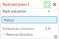
A Rack and pinion relation combines a rotational degree of freedom of a revolute Mate with a linear degree of freedom of a slider Mate to create realistic rack and pinion motion. To create a rack and pinion relation, select the Rack and pinion relation from the toolbar, then select the revolute and slider Mates that constrain your rack and pinion gears. The next step is to define the amount of linear travel. For every rotation of the pinion gear, the rack moves in a linear direction by the input amount.
To have the movement of both Rack and pinion in the opposite direction to one another, click the Reverse checkbox.
When done, click the green checkmark to exit the dialog.
To add the Rack and Pinion relation:
- Click
 .
.

- In the dialog, confirm that Rack and pinion is selected.
- Select two Mates in the main list of Mate features (or in the list of features in any of the current subassemblies). Note that selecting a Slider Mate and a Revolute Mate provides the exact degrees of freedom required by Rack and pinion.
- Specify a
degree of freedom
for that Mate, if necessary:
- When you select a Slider Mate and a Revolute Mate, no further action is needed because each has the exact degree of freedom required by Rack and pinion.
- If you select Mates with more degrees of freedom than required, a second dialog appears in which to select the desired degree of freedom for that Mate.
- Enter the desired linear value.
- Optionally check the box to reverse the direction.
Once you select a degree of freedom for the relation, you are unable to change it unless you delete the Mate from the dialog, change the Mate type, or delete the Mate and start over.
Steps
To add the Rack and pinion relation:
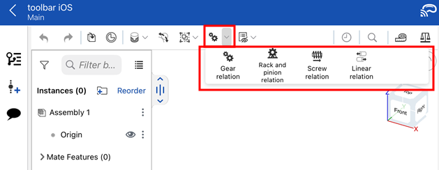
- Tap the Rack and pinion icon (
 ).
).


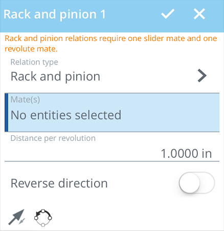
- In the dialog, confirm that Rack and pinion is selected in the Relation type field.
- Tap to select one Revolute Mate and one Slider Mate in the main list of Mate features (or in the list of features in any of the current subassemblies).
- Enter desired distance per revolution.
- Optionally, tap to reverse the direction.
-
Optionally, tap
 to Flip the primary axis, Z orientation of the instances.
-
Optionally, tap
 to Reorient the secondary axis; rotate the quadrant orientation (in the XY plane) of the instances by 90 degrees at a tap.
- Tap checkmark.
The relation only succeeds if the Mates chosen are appropriate for the types of relation chosen. Rack and pinion requires one Revolute and one Slider Mate.
Steps
To add the Rack and pinion relation:
- Tap
 .
.

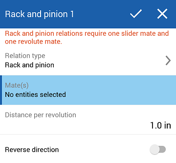
- In the dialog, confirm that Rack and pinion is selected in the Relation type field.
- Tap to select one Revolute Mate and one Slider Mate in the main list of Mate features (or in the list of features in any of the current subassemblies).
- Enter desired distance per revolution.
- Optionally, tap to reverse the direction.
- Tap checkmark.
The relation only succeeds if the Mates chosen are appropriate for the types of relation chosen. Rack and pinion requires one Revolute and one Slider Mate.