 Mate Connector
![]()
![]()
![]()
Mate connectors are local coordinate system entities located on or between entities and used within a Mate to locate and orient instances with respect to each other.
Shortcut: Ctrl+m
In the Feature toolbar:
![]()
In the Assembly toolbar:
![]()
Mate connectors are local coordinate system entities located on or between entities and used within a Mate to locate and orient instances with respect to each other.
Two instances are positioned in an assembly by creating a Mate. The two instances are positioned by aligning a Mate connector defined on one instance with a Mate connector defined on the other instance.
Mate connectors can be defined explicitly or implicitly:
- Explicit Mate connectors:
- Define using the Mate connector tool in the toolbar in an Assembly or in a Part Studio
- Listed at the highest level in the Feature list
- Can be selected from the Feature list during the creation of a mate
- Implicit Mate connectors:
- Define while creating a Mate, in an Assembly and some features in a Part Studio
- Listed at a sub-level in the Feature list in an Assembly, beneath the Mate in which it is used
- Cannot be selected from the Feature list during the creation of a Mate
When a Mate connector is used in more than one Mate, it is listed only once in the Feature list, with the first Mate that uses it (if implicit) or as its own original top-level feature in the list.
To learn more about Mates, see Mates. To learn about Mates and Mate Connectors watch the video below.
Use the shortcut key k to hide/show Mate connectors.
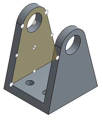
Let's take a look at adding Mates to your assemblies in Onshape. Switch over to this empty Assembly tab and insert everything from the Part Studio. All the parts are completely free to move and have all their degrees of freedom. First, fix one of the parts so that it removes all its degrees of freedom, so all other parts are mated with respect to it. To do this, right click on the part in the graphics area or features list and select Fix. Any part that is fixed has this icon next to it in the features list.
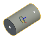
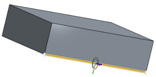
Onshape defines Mates based on the intended behavior that you would like as a result, such as fastened, revolute, slider, planar, cylindrical, pin slot, ball, and parallel. To have this part slide along the base, select the Slider Mate. Onshape prompts you for a Mate connector. These are at the heart of adding Mates. Roll your pointer over any face, and small dots appear. These are locations on faces where you establish Mate connectors. When rolling over one of these dots, a small triad appears. In addition to being locations on faces and edges, Mate connectors act as a coordinate system with their own x, y and z axes. The orientation of the axes is important, particularly for certain types of Mates. To slide this part along the blue z axis of the triad, orient the blue axis normal to the edge of the part and click to snap it into place.
For the second Mate connector, roll over the faces of the other part and the same principle applies. Pay attention to the orientation of the triad. When clicked, the part snaps into place. Notice there are icons to flip the primary and secondary axes in case you need to make any adjustments and obtain the correct results. With this single Mate added using Mate connectors, you can remove several degrees of freedom in just a few steps.
The Slider Mate is now listed in the features list. Double-click to open it and make adjustments to the Mate. For example, use the dropdown to change this Mate to any other Mate type, or to redefine any of the Mate connectors.
To fasten the spindle inside the shaft, click the Fastened Mate. This Mate type removes all degrees of freedom between any two Mate connectors, so they are bonded together. For these Mate connectors, select the point on the face inside the shaft and on the face of the spindle. Rotating one of the parts rotates them both.
Next, mate the screw with the sliding jaw. Use the Revolute or Cylindrical Mate. Revolute removes an additional degree of freedom than Cylindrical does. Click Cylindrical Mate. Roll over the cylindrical face of the jaw. There are three default Mate connector locations along its axis. Select the point at the rear of the cylinder and repeat the process for the shaft. When the parts snap into position, you may notice that previously added Mates are not solved. In these instances, click the Solve button. Finally, click the checkmark to close the Mate dialog.
At this point, the spindle is free to rotate about the Mate connector and is also free to move along the axis. This is the way the Cylindrical Mate operates. Double-click the Cylindrical Mate to open its dialog and change it to Revolute. Now, moving the spindle rotates it without moving it away from the mate point on the jaw.
Keep in mind that you can use the Mate connector tool to precisely define the location and orientation of mate points ahead of time, without having to create the Mates. You can even add Mate connectors to parts in your Part Studio so they are available when those parts are inserted into your Assemblies.
-
Click
 .
.
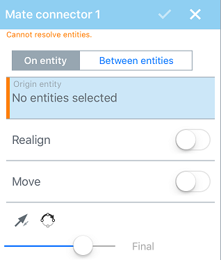
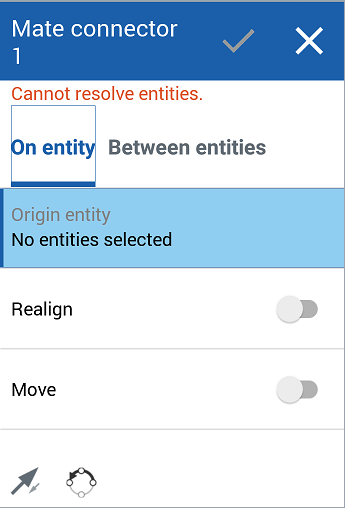
- Choose between creating a Mate connector on an entity or between entities:
- Select a point on the entity for the Mate connector:
- Roll over any face to activate the potential Mate connectors and select a point.
- Or click anywhere on a face, sketch, or surface to automatically place the Mate connector at the centroid point.
You are also able to select the Origin as an entity; select the Origin in the graphics area, or in the Instances list.
- Specify options, if desired (as shown in options examples below).
-
Click
 .
.
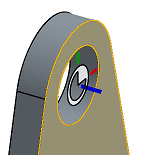
With the Mate connector dialog open, moving the cursor over an entity 'wakes up' default inference points and the inference point closest to the cursor highlights as a Mate connector. As you continue to mouse over the entity, different default inference points appear.
To lock Mate inferences when you see the one you want to select, press the Shift key when mousing.
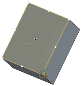
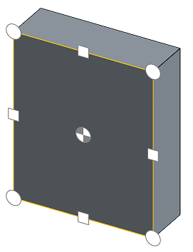
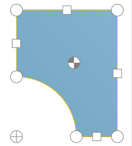
Each face and edge of an entity has default inference points:
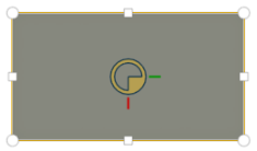
- At the centroid
- At the midpoints
- At the corners
- At the virtual sharps of conical faces:
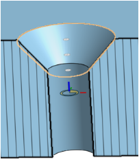
Inference points at the top, middle, bottom, and at the virtual sharp (where the sides of the conical face would meet if extended) of the conical face
- At the centroids of any region contained in a planar face (for example, holes and slots):

Before the default Mate connector is highlighted at the centroid (seen above), you might see the centroid point icon (seen below):
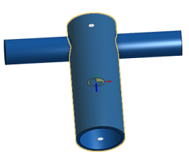
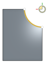
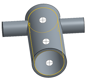
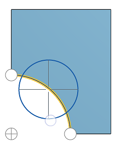
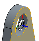
For cylindrical faces, inference points appear on the axis of the cylindrical and partial cylindrical face:
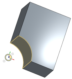
Select a planar face that has a partial cylindrical edge and the Mate connector inference points include the centroid of the axis:
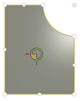
Hover over the edge of the partial cylindrical face and the default Mate connector appears at the centroid of the axis:
To zero in on a specific inferenced point or default Mate connector without waking up others as you move the cursor, use the Shift key to prevent other Mate connectors from appearing.
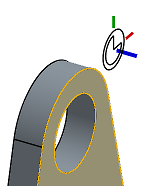
Change the orientation of the Mate connector along a primary and (optionally) a secondary axis:
- Move
- Move the Mate connector a specified distance in a specified direction. The fields are presented in this order:
- X translation
- Y translation
- Z translation
- You also have the ability to use the Rotate field to specify a rotation of a specified number of degrees.
You are able to use expressions and trigonometric functions in numeric fields in Assemblies.
The inference points for potential Mate connectors available when you select an edge or face are:
|
Planar face - Parallel to the face at every vertex, arc center, edge midpoint, and the face centroid |
|
|
Cylindrical face - Perpendicular to the face axis at the middle and ends |
|
|
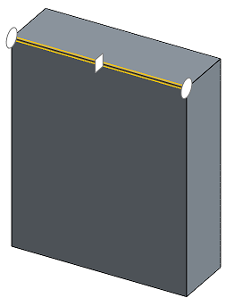
Linear edge or sketch line - Perpendicular to the line at the middle and ends |
|
|
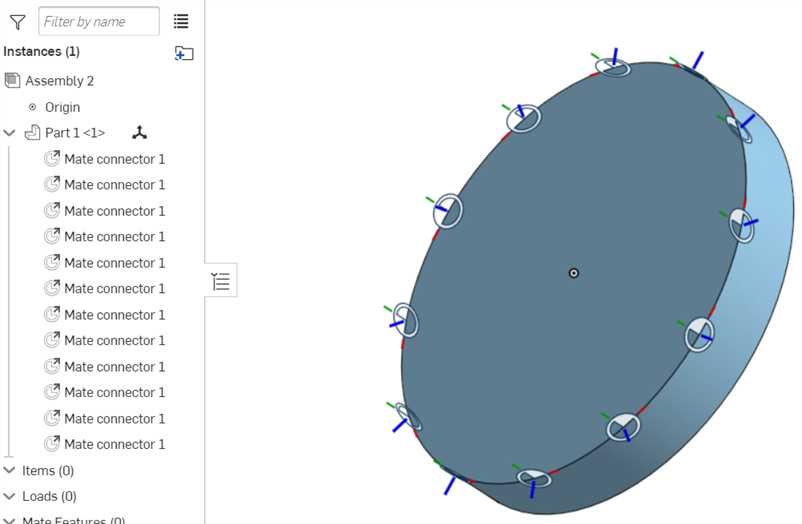
Circular edge or sketch circle - Perpendicular to the line at the middle and ends |
|
Once created, you are able to hide or show Mate connectors in both Part Studios and Assemblies:
- Use the context menu in the Feature list (Hide, Hide other Mate connectors/Show, Show all Mate connectors) - Hide other Mate connectors hides all Mate connectors but the one you have selected.
-
Use the
 icon in the Feature list to hide a specific Mate connector.
- Hiding/showing Mate connectors in a Part Studio or Assembly is exclusive to the Part Studio or Assembly. Mate connectors hidden in a Part Studio are visible when inserted into the Assembly. You are able to view Mate connectors in a Part Studio and keep them hidden in the Assembly, and vice versa.
- If the behavior is not what you expected, try flipping the primary and/or secondary axis on the Mate connector.
- Use the Shift key to keep the Mate connectors you want visible as you move the pointer to select one. This can be useful when the inferenced point for potential Mate connector you want is on or near an edge.
- All Mate connectors are listed in the Feature list; you can hide/show them, edit and adjust, change, and use different orientations of the connectors.
-
You can also select and hide/show Mate connectors in a Part Studio when working in context.
- A Mate connector may be created in both the Assembly and the Part Studio. Creating a Mate connector in the Part Studio has three advantages:
- You are able to select the origin from the Feature List in a Part Studio when defining a Mate connector.
- You are able to reference sketch entities in the Part Studio. This gives you the ability to define the Mate connector in more positions than are possible in an Assembly.
- A Mate connector defined in a Part Studio is available for reuse on every instance of that part in every assembly in which it is instanced.
- If Mate connectors are Part patterned in a Part Studio, they will all be added to the Assembly when the Part Studio is inserted. If you don't see your Mate connectors when the Part Studio is inserted into the Assembly, make sure the Part is listed as the Mate connector owner entity.
- Tap Mate connector tool.
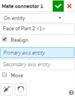
- Select origin type:
- On entity - Create a Mate connector on a part.
- Between entities - Create a Mate connector halfway between two entities on the part.
- Select origin entity.
- Optionally, toggle to realign.
If you do realign, select primary and secondary axis entities.
- Optionally, toggle to move.
If you do move, specify X,Y, and Z values.
Also select rotation axis and specify rotation angle.
- Tap the checkmark.
Each face and edge of a part has default inference points:
- At the centroid
- At the midpoints
- At the corners
For cylindrical faces, inference points appear on the axis of the cylindrical and partial cylindrical face:
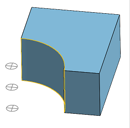
Select or hover over a planar face that has a partial cylindrical edge and the Mate connector inference points include the centroid of the axis:
Select or hover over the edge of the partial cylindrical face and default Mate connector inference points appear:
On entity
Select the origin entity then select the Mate connector inference point on which to place the Mate connector.
Between entities
Select an origin entity and the Mate connector inference point in line with where you want to place the Mate connector. Select another entity and the Mate connector is placed in line with the Mate connector inference point, between the two entities you selected.

Toggle on Realign to change the orientation of the Mate connector along a primary and (optionally) a secondary axis.
Select a primary and secondary axis along which to realign the Mate connector.
Move the Mate connector to a specified distance in a specified direction. The fields are presented in this order:
- X translation
- Y translation
- Z translation
You are also able to use a rotation axis and specify a number of degrees to rotate the Mate connector.
Once created, you are able to hide or show Mate connectors in both Part Studios and Assemblies:
- use the context menu in the Feature list (Hide, Hide other Mate connectors/Show, Show all Mate connectors) - Hide other Mate connectors hides all Mate connectors but the one you have selected.
- Use the Hide/Show icon (the eye icon) in the Feature list to hide a specific Mate connector.
- Hiding/showing Mate connectors in a Part Studio or Assembly is exclusive to the Part Studio or Assembly. Mate connectors hidden in a Part Studio are visible when inserted into the Assembly. You are able to view Mate connectors in a Part Studio and keep them hidden in the Assembly, and vice versa.
- Tap Mate connector tool.
- Select origin type:
- On entity - Create a Mate connector on a part.
- Between entities - Create a Mate connector halfway between two entities on the part.
- Select origin entity.
- Optionally, toggle to realign.
If you do realign, select primary and secondary axis entities.
- Optionally, toggle to move.
If you do move, specify X,Y, and Z values.
Also select rotation axis and specify rotation angle.
- Tap the checkmark.
Each face and edge of a part has default inference points:
- At the centroid
- At the midpoints
- At the corners
For cylindrical faces, inference points appear on the axis of the cylindrical and partial cylindrical face:
Select or hover over a planar face that has a partial cylindrical edge and the Mate connector inference points include the centroid of the axis:
Select or hover over the edge of the partial cylindrical face and default Mate connector inference points appear:
On entity
Select the origin entity then select the Mate connector inference point on which to place the Mate connector.
Between entities
Select an origin entity and the Mate connector inference point in line with where you want to place the Mate connector. Select another entity and the Mate connector is placed in line with the Mate connector inference point, between the two entities you selected.
Toggle on Realign to change the orientation of the Mate connector along a primary and (optionally) a secondary axis.
Select a primary and secondary axis along which to realign the Mate connector.
Move the Mate connector to a specified distance in a specified direction. The fields are presented in this order:
- X translation
- Y translation
- Z translation
You are also able to use a rotation axis and specify a number of degrees to rotate the Mate connector.
Once created, you are able to hide or show Mate connectors in both Part Studios and Assemblies:
- use the context menu in the Feature list (Hide, Hide other Mate connectors/Show, Show all Mate connectors) - Hide other Mate connectors hides all Mate connectors but the one you have selected.
- Use the Hide/Show icon (the eye icon) in the Feature list to hide a specific Mate connector.
- Hiding/showing Mate connectors in a Part Studio or Assembly is exclusive to the Part Studio or Assembly. Mate connectors hidden in a Part Studio are visible when inserted into the Assembly. You are able to view Mate connectors in a Part Studio and keep them hidden in the Assembly, and vice versa.
For an additional Learning center resource, follow the technical briefing article here: All the ways to use Mate connectors (Onshape account required).