 Loft
Loft
![]()
![]()
![]()
Use profiles (sketch regions or sketch curves) and optional guide curves to define shapes that smoothly transition between them. Create parts or surfaces or modify existing parts or surfaces.
A Loft feature creates a solid or a surface with a smooth transition between its profiles. It is a powerful feature that can create more complex geometry.
Depending on the selection, a Loft feature creates a solid part, surface, or thin solid.
Start a new Loft feature from the feature toolbar.
Select the Profiles for the loft. A loft requires at least two profiles but can span across more when necessary. This example uses sketches, but planar or non-planar faces or surfaces, as well as a single point, may also serve as Loft profiles. It is essential to select the profiles in sequential order.
If profiles are out of order, click the Reorder items button to enable drag handles. Once complete, click Done.
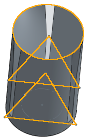
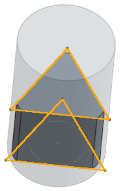
For best results, each profile in the loft should contain the same number of vertices. Consider a loft between a rectangle and a circle. One profile has four vertices, while the other has none. Onshape must assume how the two profiles are connected. This assumption can lead to undesirable twisting of the loft. To overcome this, create a profile with the same number of vertices. The split command separates a circular sketch into four segments in this example. Use the new sketch in place of the circular face to make a smoother transition between the profiles.
Select Start and End profile conditions for finer control of a Loft’s shape. Normal to profile and Tangent to profile work for all profile types, but Match tangent and Match curvature require adjacent faces to define the condition. Adjust the magnitude as needed.
Alternatively, select Normal direction or Tangent direction to define the direction of Normalcy or Tangency with a selected vector, as opposed to the profile or a face.
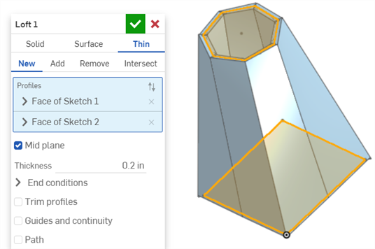
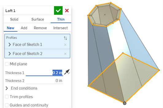
Use the same process to create a Surface or Thin loft. For a Thin loft, set the thickness on either side of the profile. Alternatively, enable the Mid plane option to center it on the profile.
Loft profiles cannot contain multiple contours. Ensure all loft profiles are single contours. When a profile with additional contours is selected, Onshape displays it in red, indicating it is unsuitable for a Loft feature.
- Click
 .
.
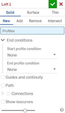
- Select Solid Creation type.
- Specify a Result operation type:
- New - Create a new solid.
- Add - Add to an existing solid.
- Remove - Subtract from an existing solid.
- Intersect - Keep only the intersection of two (or more) solids.
- Select
profiles
(a region, face, edge, or point) and then optional cross-sections (in order of the loft direction) and finally the end (region, face, edge, or point).
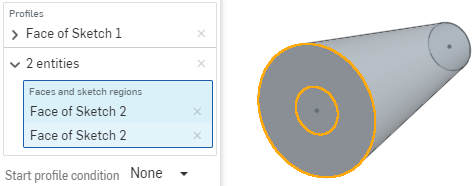
To select a set of tangentially connected curves as a single chain, click the arrow next to the desired selection in the dialog to expand the selection field. (A blue field is an active field.) Select more curves to create a composite selection.
For example: To select both circles in the end loft position, select the first circle, then click in the field where the first selection appears and then click the second selection:
- To refine the shape further, select a
Start and/or End Profile condition
to define the derivative constraints on the start and end profiles:
- Normal to profile
- Causes the loft to touch the profile with tangents parallel to the profile's normal

- Tangent to profile
- Causes the loft to touch the profile tangent to the profile plane.

- Match tangent - Causes the loft to match the tangents of model faces adjacent to the profile face (if available). Optionally, when selected, the Adjacent faces field is enabled. Pick any face in which underlying geometry is coincident with at least one profile part's curve (the face and edge do not need to intersect or be part of the same part).
- Match curvature - Causes the loft to match the curvature of model faces adjacent to the profile face (if available). Optionally, when selected, the Adjacent faces field is enabled. Pick any face in which underlying geometry is coincident with at least one profile part's curve (the face and edge do not need to intersect or be part of the same part).
- Normal direction - Causes the loft profile to be normal to a selected direction, for example, a line or mate connector. Optionally, enter a positive or negative Magnitude value to adjust the surface shape according to one profile or another.
- Tangent direction - Causes the loft profile to be tangent to a selected direction, for example, a line or mate connector. Optionally, enter a positive or negative Magnitude value to adjust the surface shape according to one profile or another.
- Normal to profile
- Causes the loft to touch the profile with tangents parallel to the profile's normal
- Optionally, use a
guide
curve or curves for the loft to follow; it is not necessary for the guide curves to be touching the outsides of the profiles, only for them to intersect.
- Check the Guides and continuity box.
- Select the curve (or curves) to act as guides.
- (Optional) To select tangentially connected curves as a single guide, click the down arrow next to the selected guide to open the field for more selections. Selected guides must be tangent continuous (G1) curves that intersect each profile boundary.
- Make additional selections:
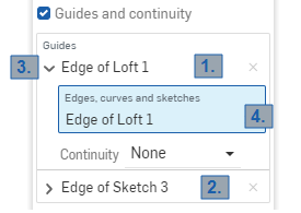
1 and 2: Each of these is a single guide selection (“Edge of Loft 1” and “Edge of Sketch 3”).
3: Click the arrow next to the guide name to expand the field.
4: The blue highlighting indicates that field is active. At this point, you can select more adjacent curves to create a composite guide selection.
- (Optional) For further definition, use the Continuity condition on the guide. Continuity can be:
- Normal to guide - Causes the loft to touch the guide with tangents parallel to the guide's normal.
- Tangent to guide - Causes the loft to touch the guide with tangents on the guide's plane.
- Match tangent - Causes the loft to match the face tangent of the guides adjacent to the profile.
- Match curvature - Causes the curvature of the loft faces to match the curvature of the guides adjacent to the profile.
Make sure that your sketch is consistent with what you are selecting, if the sketch is inconsistent with Match tangent and it is selected, the loft will fail. The same is true for Match curvature.
- Make additional selections:
- To create a centerline equivalent, select a
Path
for the loft to follow (and create intermediate sections along the path for the loft to reference).
- Click the box next to Path.
- Select edges, curves, and sketches to act as the path (centerline guide) of the loft.
- Specify the section count (number of intermediate sections) to be used along the path. The more sections used, the more closely the path is followed.
For example: Straight line selected as the path, section count = 3
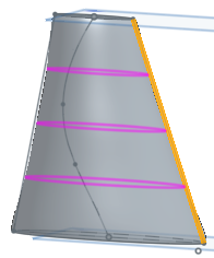
Spline selected as the path, section count = 10
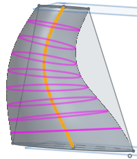
The Loft path option is not compatible with lofts that contain non-planar profiles.
- Optionally, select
Connections
to have more control on the twist of the resulting surface. If there are guides, those are used for alignment, if not Onshape estimates the proximity within the existing vertices. It is best to have at least two vertices on each profile and use the matching vertices to control twist.
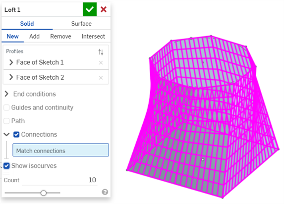
- Click Connections. The automatic connections are displayed in magenta. Automatic connections are only visible if there are no Match connection entries:
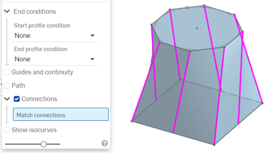
- Select an alternate set of vertices/edges to use:
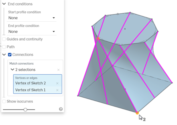
Each connection must have two selections. To add a second selection for a connection, click in the Vertices or edges box (it turns blue when selected). To add another set of connections, click in the Connections box first (also turns blue when selected), then select the second pair of vertices/edges:
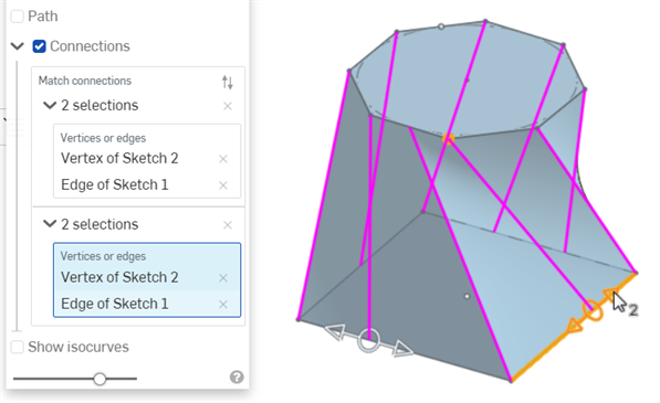
Once a connection is created, you can use the manipulator to drag to adjust the resulting shape (also shown in the image above).
- Click Connections. The automatic connections are displayed in magenta. Automatic connections are only visible if there are no Match connection entries:
- Optionally, select Show isocurves to show a mesh overlay on the loft faces.
The Count determines the number of isocurves per face.
- For Add, Remove, or Intersect result operations, optionally check Merge with all, or select a Merge scope to select parts with which to merge the lofted part. See more on Merge scope below.
-
Click
 .
.
Onshape remembers the selection (Solid, Surface, or Thin) and opens the dialog with the last selected option in subsequent operations.
- Click
 .
.
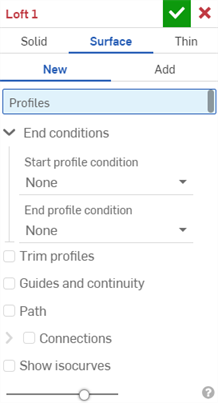
- Select Surface Creation type.
- Specify a Result operation type:
- New - Create a new surface.
- Add - Add to an existing surface.
-
Select Profiles (a region, face, edge, or point) and then optional cross-sections (in order of the loft direction) and finally the end (region, face, edge, or point).
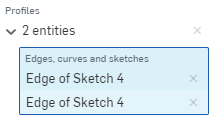
To select a set of tangentially connected curves as a single chain, click the arrow next to the desired selection in the dialog to expand the selection field. (A blue field is an active field.) Select more curves to create a composite selection.
- To refine the shape further, select a
Start and/or End profile condition to define the derivative constraints on the start and end profiles:
- Normal to profile - Causes the loft to touch the profile with tangents parallel to the profile's normal.
- Tangent to profile - Causes the loft to touch the profile with tangents on the profile plane.
- Match tangent - Causes the loft to match the tangents of model faces adjacent to the profile face (if available). Optionally, when selected, the Adjacent faces field is enabled. Pick any face in which underlying geometry is coincident with at least one profile part's curve (the face and edge do not need to intersect or be part of the same part).
- Match curvature - Causes the loft to match the curvature of model faces adjacent to the profile face (if available). Optionally, when selected, the Adjacent faces field is enabled. Pick any face in which underlying geometry is coincident with at least one profile part's curve (the face and edge do not need to intersect or be part of the same part).
- Normal direction - Causes the loft profile to be normal to a selected direction, for example, a line or mate connector. Optionally, enter a positive or negative Magnitude value to adjust the surface shape according to one profile or another.
- Tangent direction - Causes the loft profile to be tangent to a selected direction, for example, a line or mate connector. Optionally, enter a positive or negative Magnitude value to adjust the surface shape according to one profile or another.
-
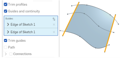
Trim profiles - Trim the loft operation to the intersection of the profiles and the guides, along the profiles. The image below shows the profiles trimmed, and the Guides selected:
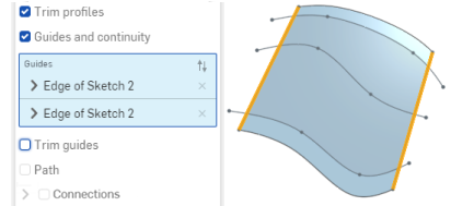
The image below shows both Trim guides and Trim profiles selected, which trims the loft along both the guides and the profiles:
- Optionally, use a
guide
curve or curves for the loft to follow; guide curves must be touching the outsides of the profiles, not the centers.
- Check the Guides and continuity box.
- Select the curve (or curves) to act as guides.
- To select tangentially connected curves as a single guide, click the down arrow next to the selected guide to open the field for more selections. Selected guides must be tangent continuous (G1) curves that intersect each profile boundary.
- Make additional selections:

1 and 2: Each of these is a single guide selection (“Edge of Loft 1” and “Edge of Sketch 3”).
3: Click the arrow next to the guide name to expand the field.
4: The blue highlighting indicates that field is active. At this point, you can select more adjacent curves to create a composite guide selection.
(Optional) For further definition, use the Continuity condition on the guide. Continuity can be:
- Normal to guide - Causes the loft to touch the guide with tangents parallel to the guide's normal.
- Tangent to guide - Causes the loft to touch the guide with tangents on the guide's plane.
- Match tangent - Causes the loft to match the face tangent of the guides adjacent to the profile.
- Match curvature - Causes the curvature of the loft faces to match the curvature of the guides adjacent to the profile.
Make sure that your sketch is consistent with what you are selecting, if the sketch is inconsistent with Match tangent and it is selected, the loft will fail. The same is true for Match curvature.
- Make additional selections:
-
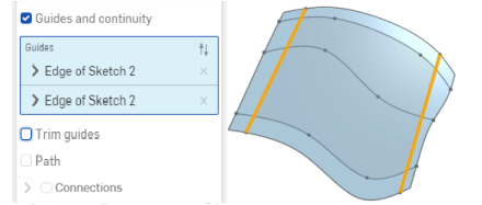
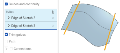
Trim guides becomes available when Guides and continuity is selected. This option allows you to control how the guides influence the loft operation, specifically to trim the loft operation to the boundaries of the guides.
The image below is without any Trim selected, the loft extends the length of the profiles and also the length of the guides (which are highlighted below):
The image below is with Trim guides selected, the loft is trimmed to the intersection of the profiles and the guides, along the guides:
- To create a centerline equivalent, select a
Path
for the loft to follow (and create intermediate sections along the path for the loft to reference).
- Click the box next to Path.
- Select edges, curves, and sketches to act as the path (centerline guide) of the loft.
- Specify the section count (number of intermediate sections) to be used along the path. The more sections used, the more closely the path is followed.
For example: Straight line selected as the path, section count = 3

Spline selected as the path, section count = 10

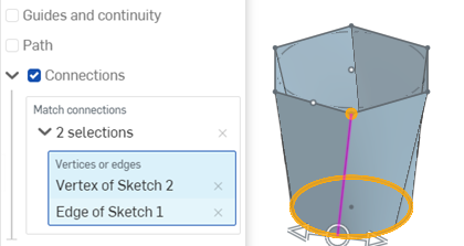
- Optionally, select
Connections
to have more control on the twist of the resulting surface. If there are guides, those are used for alignment, if there are no guides then Onshape estimates the proximity within the existing vertices. It is best to have at least two vertices on each profile and use the matching vertices to control twist:
- Click Connections. The automatic connections are displayed in magenta. Automatic connections are only visible if there are no Match connection entries.
- Select one set of vertices (one vertex on each region/face/edge/point) or a vertex and a curve:
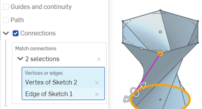
Use the manipulator to change the alignment of the vertices/edges:
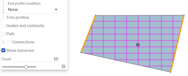
- Optionally, select Show isocurves to show a mesh overlay on the loft surface.
The Count determines the number of isocurves.
- For the Add result operation, optionally check Merge with all, or select a Merge scope to select parts with which to merge the new (additional) part. See more on Merge scope below.
-
Click
 .
.
Onshape remembers the selection (Solid, Surface, or Thin) and opens the dialog with the last selected option in subsequent operations.
- Click
 .
.
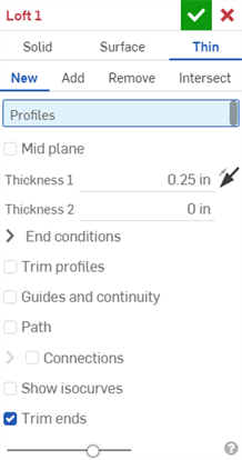
- Select Thin Creation type.
-
Specify a Result operation type:
- New - Create a new solid.
- Add - Add to an existing solid.
- Remove - Subtract from an existing solid.
- Intersect - Keep only the intersection of two (or more) solids.
-
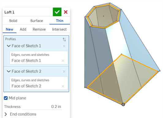
Select Profiles (a region, face, edge, or point) and then optional cross-sections (in order of the loft direction) and finally the end (region, face, edge, or point).
Select more profiles to create a composite selection.
-
Do one of the following:
-
To use a symmetric thickness, check the Mid plane option and then enter the Thickness value. The loft will extend equally in both directions from the midplane.
-
To specify individual wall thicknesses, uncheck the Mid plane option. Then, enter the Thickness 1 wall value and Thickness 2 wall value. Click the Flip wall arrow to flip Thickness 1 with Thickness 2.
-
- To refine the shape further, select a
Start and/or End profile condition to define the derivative constraints on the start and end profiles:
- Normal to profile
- Causes the loft to touch the profile with tangents parallel to the profile's normal

- Tangent to profile
- Causes the loft to touch the profile tangent to the profile plane.

- Match tangent - Causes the loft to match the tangents of model faces adjacent to the profile face (if available). Optionally, when selected, the Adjacent faces field is enabled. Pick any face in which underlying geometry is coincident with at least one profile part's curve (the face and edge do not need to intersect or be part of the same part).
- Match curvature - Causes the loft to match the curvature of model faces adjacent to the profile face (if available). Optionally, when selected, the Adjacent faces field is enabled. Pick any face in which underlying geometry is coincident with at least one profile part's curve (the face and edge do not need to intersect or be part of the same part).
- Normal direction - Causes the loft profile to be normal to a selected direction, for example, a line or mate connector. Optionally, enter a positive or negative Magnitude value to adjust the surface shape according to one profile or another.
- Tangent direction - Causes the loft profile to be tangent to a selected direction, for example, a line or mate connector. Optionally, enter a positive or negative Magnitude value to adjust the surface shape according to one profile or another.
- Normal to profile
- Causes the loft to touch the profile with tangents parallel to the profile's normal
-
Trim profiles - Trim the loft operation to the intersection of the profiles and the guides, along the profiles. The image below shows the profiles trimmed, and the Guides selected:

The image below shows both Trim guides and Trim profiles selected, which trims the loft along both the guides and the profiles:

- Optionally, use a
guide
curve or curves for the loft to follow; guide curves must be touching the outsides of the profiles, not the centers.
- Check the Guides and continuity box.
- Select the curve (or curves) to act as guides.
- (Optional) To select tangentially connected curves as a single guide, click the down arrow next to the selected guide to open the field for more selections.
Selected guides must be tangent continuous (G1) curves that intersect each profile boundary.
- Make additional selections:

1 and 2: Each of these is a single guide selection (“Edge of Loft 1” and “Edge of Sketch 3”).
3: Click the arrow next to the guide name to expand the field.
4: The blue highlighting indicates that field is active. At this point, you can select more adjacent curves to create a composite guide selection.
- (Optional) For further definition, use the Continuity condition on the guide. Continuity can be:
- Normal to guide - Causes the loft to touch the guide with tangents parallel to the guide's normal.
- Tangent to guide - Causes the loft to touch the guide with tangents on the guide's plane.
- Match tangent - Causes the loft to match the face tangent of the guides adjacent to the profile.
- Match curvature - Causes the curvature of the loft faces to match the curvature of the guides adjacent to the profile.
Make sure that your sketch is consistent with what you are selecting, if the sketch is inconsistent with Match tangent and it is selected, the loft will fail. The same is true for Match curvature.
- Make additional selections:
-
Trim guides becomes available when Guides and continuity is selected. This option allows you to control how the guides influence the loft operation, specifically to trim the loft operation to the boundaries of the guides.
The image below is without any Trim selected, the loft extends the length of the profiles and also the length of the guides (which are highlighted below):

The image below is with Trim guides selected, the loft is trimmed to the intersection of the profiles and the guides, along the guides:

- To create a centerline equivalent, select a
Path
for the loft to follow (and create intermediate sections along the path for the loft to reference).
- Click the Path box.
- Select edges, curves, and sketches to act as the path (centerline guide) of the loft.
- Specify the section count (number of intermediate sections) to be used along the path. The more sections used, the more closely the path is followed.
For example: Straight line selected as the path, section count = 3

Spline selected as the path, section count = 10

- Optionally, select
Connections
to have more control on the twist of the resulting surface. If there are guides, those are used for alignment, if there are no guides then Onshape estimates the proximity within the existing vertices. It is best to have at least two vertices on each profile and use the matching vertices to control twist.
The automatic connections are displayed in magenta. Automatic connections are only visible if there are no Match connection entries.
- Select one set of vertices (one vertex on each region/face/edge/point) or a vertex and a curve:
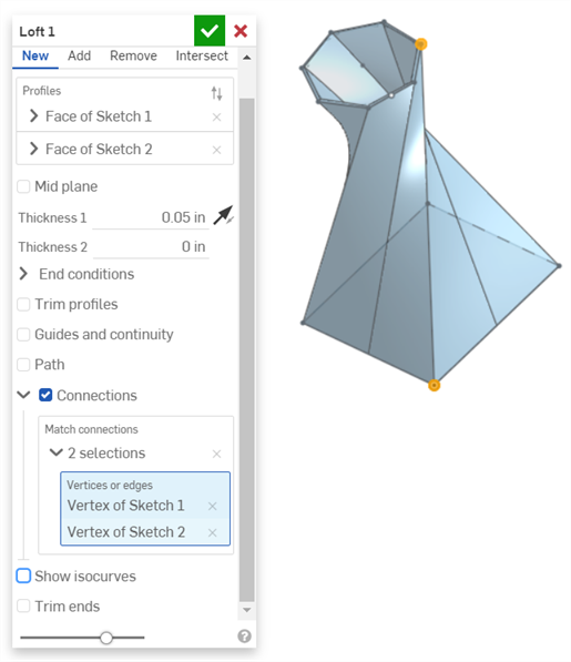
Use the manipulator to change the alignment of the vertices/edges:
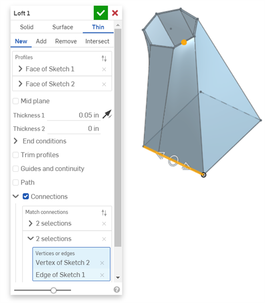
- Select one set of vertices (one vertex on each region/face/edge/point) or a vertex and a curve:
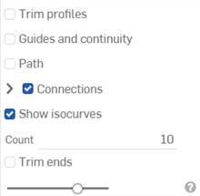
- Optionally, select Show isocurves to show a mesh overlay on the loft surface.
The Count determines the number of isocurves.
-
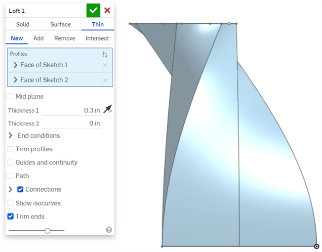
Check the Trim ends option to start and terminate the loft at the profiles.
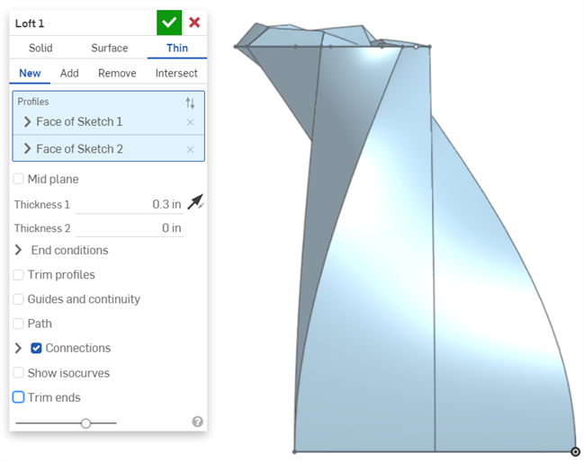
Uncheck it to create end faces tangent to the profiles.
- For the Add result operation, optionally check Merge with all, or select a Merge scope to select parts with which to merge the new (additional) part.
-
Click
 .
.
Onshape remembers the selection (Solid, Surface, or Thin) and opens the dialog with the last selected option in subsequent operations.
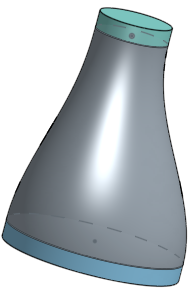
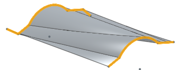
Surface / Add / Guides / Match curvature - Create material and add it to the existing material.

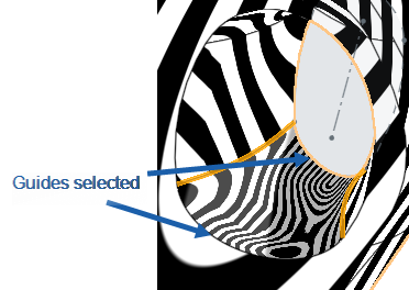
New - Create new material that results in a new part or surface.
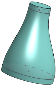
Add - Create material and add to the existing material. (This example is merge with all existing material; you could also select one part as the merge scope.)
-
When adding material, you have the option to merge that material with other parts that touch or intersect its geometry.
-
If the geometry touches or intersects with only one part then that part is automatically added to the merge scope.
- If multiple parts touch or intersect the geometry, then there is ambiguity and you must select which parts to merge with (the merge scope).
- A shortcut to selecting multiple touching or intersecting parts, you can check Merge with all to add all touching or intersecting parts to the merge scope.
- Note that if the Boolean is set to Add, Remove, or Intersect and nothing is set in the merge scope, the feature will result in an error. For New, no merge scope is available since New does not boolean the result.
Take material away from existing material by selecting sketches along the loft profile; not available for surfaces.
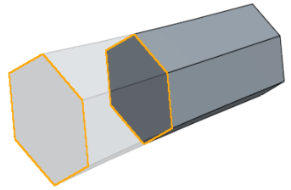
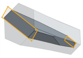
Leave material only where selected geometry overlaps; if necessary, select Merge with all to complete the process; not available for surfaces.
Select a path to use as a centerline equivalent (guide) for the loft and as a way to control the global shape of the loft. It is not necessary for this guide to be at the center. Specify the number of intermediate sections along the path to fine-tune the shape of the loft along the path.
Loft with no path:
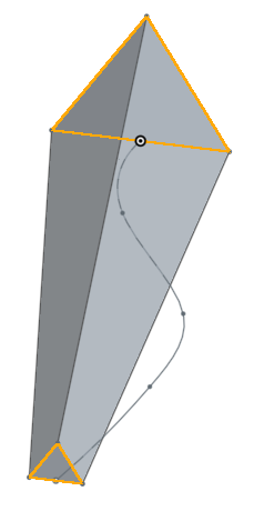
Loft with path and 2 intermediate sections:
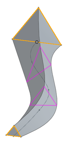
Loft with path and 20 intermediate sections:
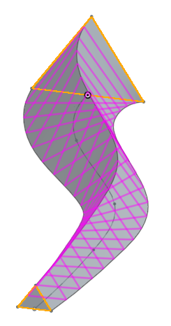
Merge scope is available with parts and surfaces and allows you to select the specific part or surface with which to merge the newly created part or surface. By default, Merge all is selected. You are able to uncheck that box to access the Merge scope field, then select the part or surface with which to merge. Surfaces must be merged with surfaces and parts with parts.
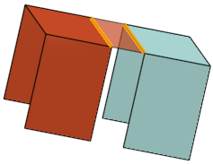

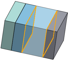
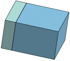
Merge scope: with all
Merge extrusion with all parts it intersects
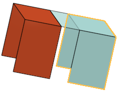
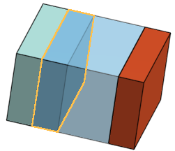
Merge scope: particular part
Select a specific part with which to merge
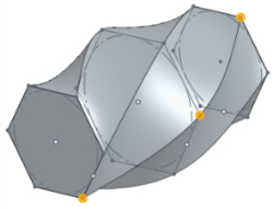
Select one set of vertices and/or edges (one on each profile).
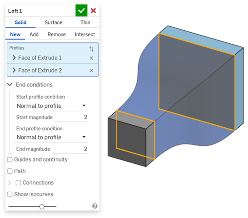
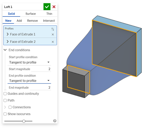
Select start profile condition and end profile condition (derivative constraints on the start and end profiles). For each end condition (start profile and end profile), you are able to specify a magnitude.
Normal to profile - Causes the loft to touch the profile with tangents parallel to the profile's normal
Tangent to profile - Causes the loft to touch the profile with tangents on the profile plane
Match tangent - Causes the loft to match the tangents of model faces adjacent to the profile face (if available).
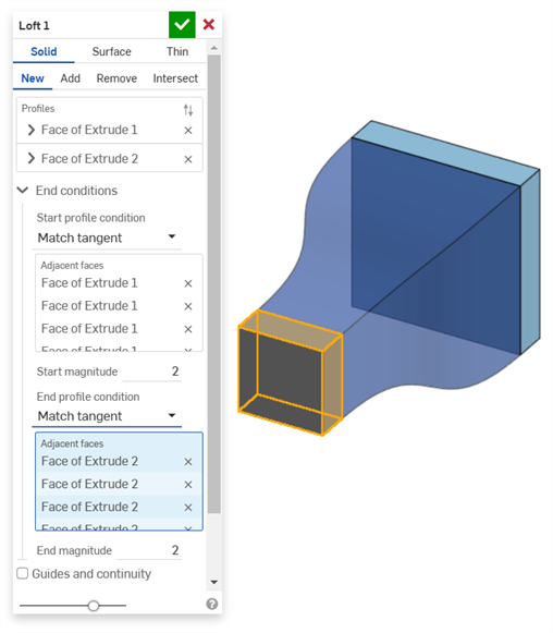
Optionally, when selected, the Adjacent faces field is enabled. Pick any face in which underlying geometry is coincident with at least one profile part's curve (the face and edge do not need to intersect or be part of the same part).
Match curvature - Causes the loft to match the curvature of model faces adjacent to the profile face (if available).
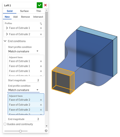
Optionally, when selected, the Adjacent faces field is enabled. Pick any face in which underlying geometry is coincident with at least one profile part's curve (the face and edge do not need to intersect or be part of the same part).
Normal direction - Causes the loft profile to be normal to a selected direction, for example, a line or mate connector. Optionally, enter a positive or negative Magnitude value to adjust the surface shape according to one profile or another.
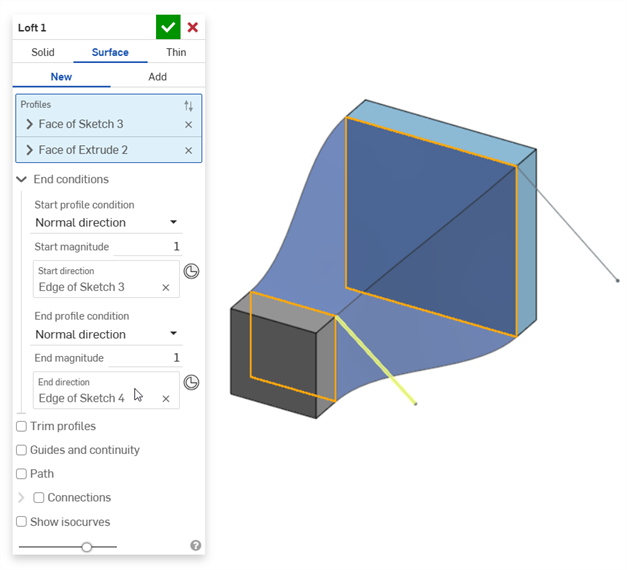
Tangent direction - Causes the loft profile to be tangent to a selected direction, for example, a line or mate connector. Optionally, enter a positive or negative Magnitude value to adjust the surface shape according to one profile or another.
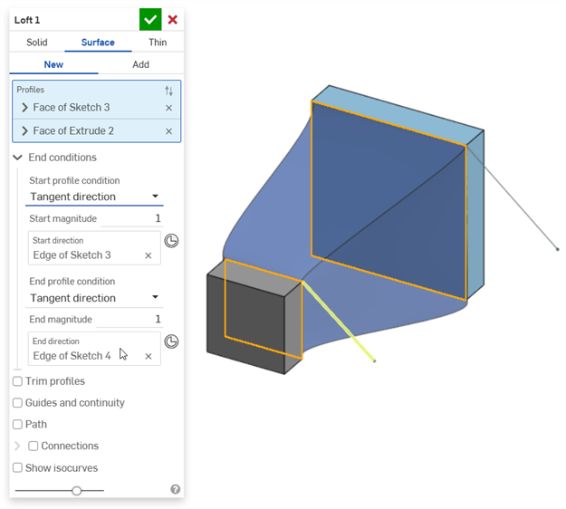
- For best results, all profiles should have the same number of curve segments.
- Vertex selection must be one vertex from each profile.
- Profiles (regions) and guides to be used in a loft operation each must be a single entry in the entry field.
- When working with multi-edge guide curves make sure one sketch defines the guide; select it from the Feature list.
- Make sure to select profiles (regions, faces, edges, or points) in the correct order from the start of the loft to the end.
- Guide curves need to be smooth (multi-edge curves must be tangent), and they must touch the profile (use Coincident or Pierce constraints).
- After creating the loft, use the Final button during editing to visualize the result and fine tune the operation.
- Nested loops in profiles are currently not supported.
- To select tangentially connected curves as a single guide, select them from the Feature list as a complete sketch, or from the Parts list as Curves.
- Tap the Loft tool icon (
 ).
).
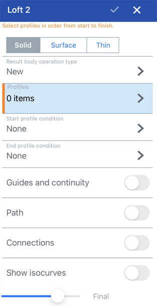
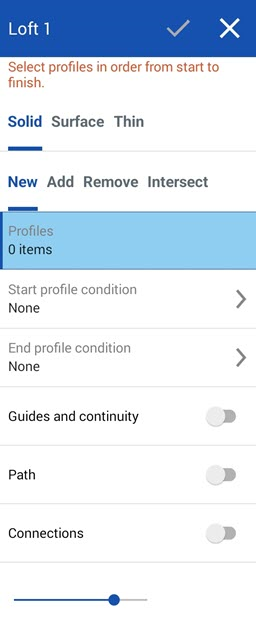
Loft dialog for iOS (left) and Android (right)
- Select Creation type:
- Solid - Create parts or modify existing parts.
- Surface - Create a surface along a sketch curve.
- Thin - Creates a thin loft.
- Select a Result body operation type:
- New - Create new material that results in a new part.
- Add - Create new material and add to the existing material.
- Remove - Take material away from a part.
- Intersect - Leave material only where intersections exist.
- Profiles - Select Profiles to loft:
First select the start profile (a region, face, edge, or point), and then optional cross-sections (in order of the loft direction) to help bound the loft, and finally the end (a region, face, edge, or point).
- Start and End profile condition - Select a Start profile condition and End profile condition (derivative constraints on the start and end profiles to help define the loft). For each condition, you are able to specify a magnitude (use the number pad to change these values):
- None
- Normal to profile - Causes the loft to touch the profile with tangents parallel to the profile's normal
- Tangent to profile - Causes the loft to touch the profile with tangents on the profile plane
- Match tangent - Causes the loft to match the tangents of model faces adjacent to the profile face (if available). Optionally, when selected, the Adjacent faces field is enabled. Pick any face in which underlying geometry is coincident with at least one profile part's curve (the face and edge do not need to intersect or be part of the same part).
- Match curvature - Causes the loft to match the curvature of model faces adjacent to the profile face (if available). Optionally, when selected, the Adjacent faces field is enabled. Pick any face in which underlying geometry is coincident with at least one profile part's curve (the face and edge do not need to intersect or be part of the same part).
- Normal direction - Causes the loft profile to be normal to a selected direction, for example, a line or mate connector.
- Tangent direction - Causes the loft profile to be tangent to a selected direction, for example, a line or mate connector.
- Guides and continuity - Select the guide lines (guide lines must be touching the outsides of the profiles, not the centers). To select a set of connected curves as a single chain, select them from the Feature list as a complete sketch.
- Path - Select a path (centerline guide) for the loft to follow (and create intermediate sections along the path for the loft to reference).
- Tap to toggle Path.
- Select edges, curves, and sketches to act as the path (centerline guide) of the loft.
- Specify the section count (number of intermediate sections) to be used along the path. The more sections used, the more closely the path is followed.
- Connections - Select optional vertices to match (to define corresponding locations on each profile):
- Tap to toggle Connections.
- Select one set of vertices (one vertex or edge on each region/face/edge/point).
- Show isocurves - Optionally, select this option to show a mesh overlay on the loft surface. The Count determines the number of isocurves.
- Click the checkmark to accept the Loft.
For more information on the Loft feature and examples, see the Loft: Desktop section above.