![]()
![]()
![]()
Available in: Part Studio, Assembly, Drawing
The Onshape Measure tool is available in Part Studios, assemblies, and drawings, for measuring sketches, parts, assemblies, curves, and surfaces. The Measure tool appears in the bottom right corner of the interface.
The Measure tool displays measurements dynamically whenever you select entities.
You can filter which measurements are shown by selecting a Measure type from the first dropdown. If pre-selections are made, the tool displays some information. For more information, click the icon to open the dialog:
In addition, selecting any entity from the graphics area also automatically shows the pertinent measurements without having to explicitly open the Measure dialog.
You can also use the Measure tool on faces, edges, and vertices while in a Section view.
This video explains how the Onshape Measure tool is used. The Measure tool is available in the Part Studio, for sketches and parts, and in Assemblies, for parts and assemblies. The Measure tool appears in the bottom right corner of the interface.
The Measure tool displays measurements dynamically whenever you select entities. Select any entity and the Measure tool shows measurements for the single entity. Use the dropdowns to select measurement type, measurement length, and measurement angle unit.
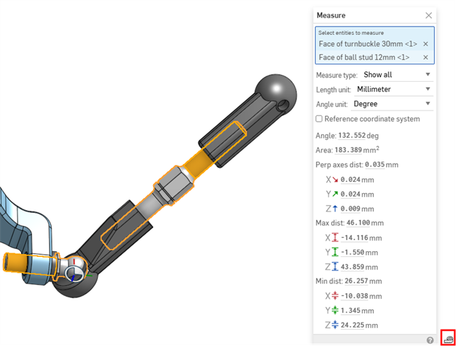
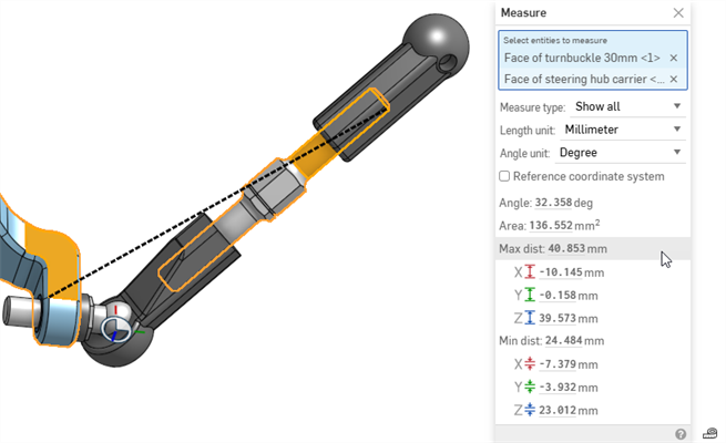
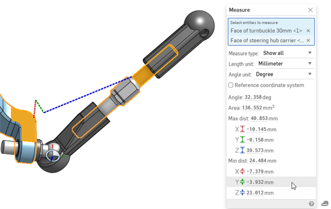
Optionally, select another entity. The Measure tool shows center-to-center, maximum-to-maximum, and minimum-to-minimum measurements between the two entities. Hovering over the measurement information displays the measurement in the graphics area. Sketch entity icons indicate the entity type. Center, maximum, and minimum distances between entities are shown as bold dotted lines. Changes in x are shown in red, changes in y are shown in green, and changes in z are shown in blue. Center distances between the two entities are shown as a black dotted line. The same with maximum distance, and the same with the minimum distance between the two entities.
Shortcut: [
- Select the entity or entities you want to measure. You can also select these after opening the Measure tool.
- Click the Measure tool icon
 in the bottom-right corner of the page. The Measure tool shows measurements for the selected entity or entities:
- Use the dropdowns to select Measure type, Length unit, and/or Angle unit. These can all be changed at any time.
- Optionally, select another entity. The Measure tool shows center-to-center, maximum-to-maximum, and minimum-to-minimum measurements between the entities.
When a sketch entity is selected in a Part Studio, a sketch entity icon indicates the type.
Measuring more than two entities in an assembly will provide you with the minimum distance, maximum distance, total area, center axes distance, or length of those entities.
-
Measure type - Filters the type of measurements displayed in the Measure dialog. Options are Show all, Position, Center position, Min distance, Max distance, Length, Diameter, Radius, Angle, Face tangent angle, Curvature deviation, or Surface area.
-
Length unit - Select the length unit. Options are Centimeter, Foot, Inch, Meter, Millimeter, or Yard.
-
Angle unit - Select the angle unit type: Degree or Radian.
-
Diameter - Diameter of an arc or circle.
-
Radius - Radius of an arc.
-
Center Dist. - The center distance between two entities.
-
Perp axes angle - Perpendicular axes angle between two entities.
-
Area - Area of a surface.
-
Face tangent angle - Tangent angle between a selected surface and a line that meets the surface.
-
Curvature deviation - Deviation between a selected surface and a line that meets the surface.
-
Center - The center dimensions for an arc or circle (X, Y, Z).
-
Center Dist. - Center distance between two entities (X, Y, Z).
-
Min Dist. - Minimum distance between two entities (X, Y, Z).
-
Max Dist. - Maximum distance between two entities (X, Y, Z).
-
Min Rad Pt. - Minimum elliptical radial point (X, Y, Z).
-
Max Rad Pt. - Maximum elliptical radial point (X, Y, Z).
-
Length - Length of an entity; for example, the length of a line, or circumference of a circle.
-
Point - Location of a point, vertex, or mate connector (X, Y, Z).
You can use the information displayed in the Measure tool to enter values elsewhere in the system, for example, as a dimension:
- With the Measure tool open, click to highlight the value you want to copy.
- Click once to capture the maximum precision value.
- Click a second time to capture the lower precision.
- Use keyboard shortcuts to copy the value.
When you hover over measurement information in the Measure tool, the measurement is visualized in the graphics area, depicting the exact measurement referred to. For example:
|
Sketch entity icon Indicates the type of entity selected |
|
|
Bold dotted line Center, maximum, or minimum distance between entities:
When measuring to the center of a circle, you can select a planar face, edge, or edge of a cylinder. Click a distance in the Measure tool to keep its line visible in the graphics area. Click it again to show the line only on hover. |
Center, Max, and Min measurements displayed with a bold, black dotted line
X, Y, and Z measurements displayed with bold red, green, and blue dotted lines, respectively |
|
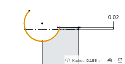
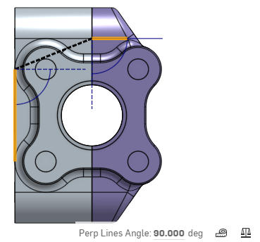
Thin dotted line Indicates an angle |
|
|
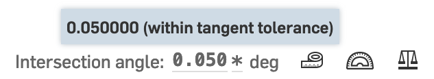
Star (✱) Indicates the value is within the coincident/tangent tolerance, even though it's non-zero. Note that non-zero values can still affect the quality of downstream geometry, even if they are within tolerance. |
Star next to non-zero value within tangent tolerance. |
When the Sheet metal table and flat view panel (![]() ) is open, the Measure dialog shows information for both the sheet metal model in the Part Studio and in flat view.
) is open, the Measure dialog shows information for both the sheet metal model in the Part Studio and in flat view.
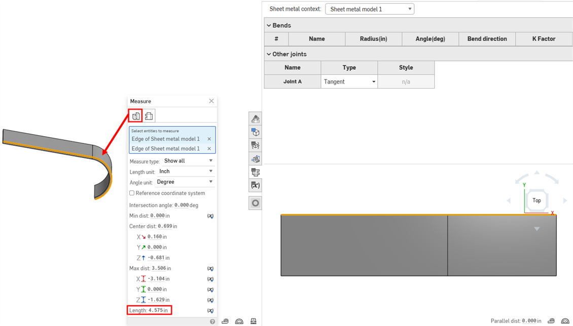
Select the Part Studio tab to measure the sheet metal model in the Part Studio.
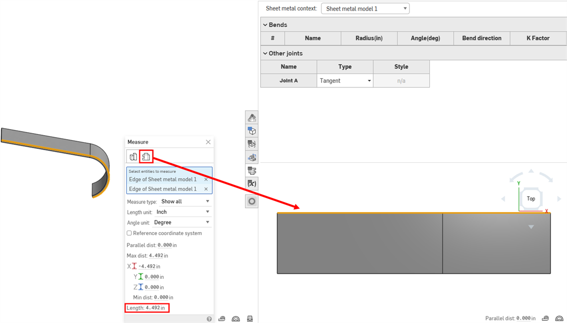
Select the Flat View tab to measure the sheet metal model in flat view.
(Available for desktop browser only.)
You can change the Measure tool's frame of reference from the origin to one defined by a mate connector.
In the Measure tool, select the Reference coordinate system option. The Mate connector for reference coordinate system field appears:
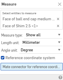
Select the mate connector to use as the new frame of reference. The Measure tool updates its calculations based on the new orientation.
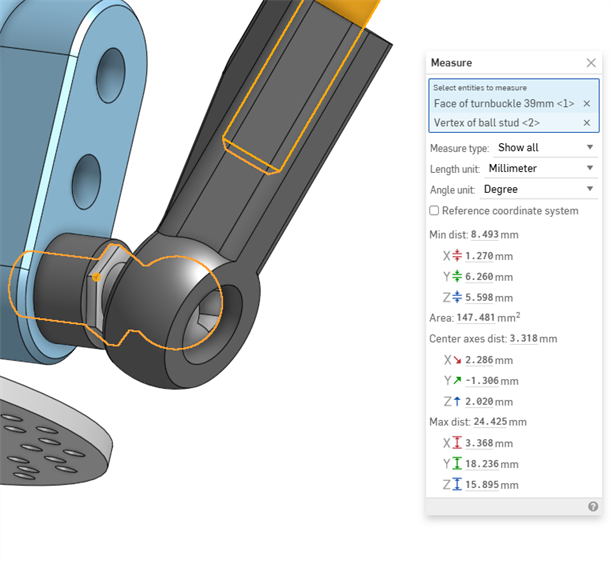
Frame of reference defaults to the origin
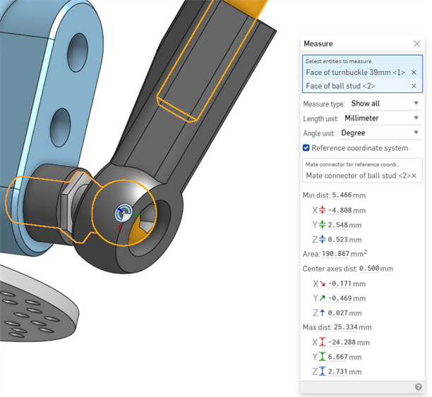
Custom frame of reference defined by a mate connector
Part Studios only
To add a variable for the current measurement, click the variable icon to the right of the measurement:
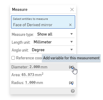
This opens the Variable dialog, pre-populated with your selections to get the listed measurement . See the Variable topic for more information on variables.
Assemblies only
If the Measure tool is opened, measurement values are updated dynamically as parts are dragged on screen. Some examples are:
-
If a circular edge or mate connector of a part is selected, the center or point location relative to the origin point updates as the part is moved.
-
If the origin point and a part entity (edge, face, vertex, mate connector) are both selected, the distance between the entity and the origin point updates as the part is moved.
-
If one part is fixed and another is not, selecting an entity from the fixed part (edge, face, vertex, mate connector) and an entity from the non-fixed part (edge, face, vertex, mate connector) updates the distance values between the two selected entities as the non-fixed part is moved.
Dynamic updating does not work when using Section view.
Obtain a measurement between points, lines, arc and circles in a drawing.
Shortcut: [
Steps
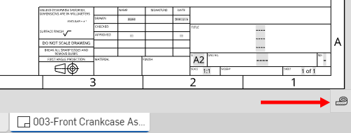
- Click
(in the bottom right corner of the drawing) to open the Measure dialog in a drawing.
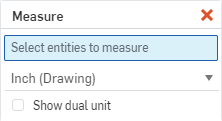
- Select the entity to measure, or multiple entities to measure between.
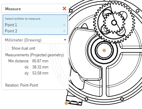
- Select the unit of measure from the dropdown: the document's default units are indicated by (Drawing). This is especially useful for users with view-only permission, to obtain measurements in the units necessary.
- Optionally elect to show dual units, if desired. A second measurement appears beside the first measurement:
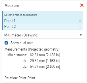
- The measurements of the projected geometry are displayed in the dialog box, and axes are indicated.
- The type of relation is shown, in the above example it is point-to-point.
- Click the red x to close the dialog.
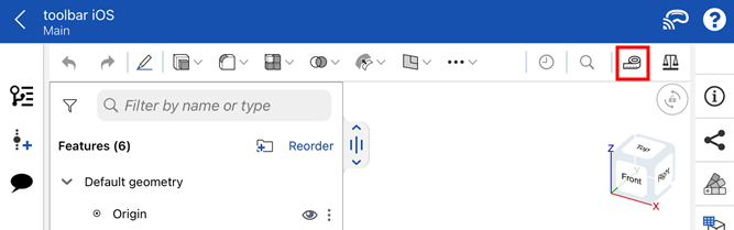
The images below are from iOS. The workflow is the same for both iOS and Android.
![]()
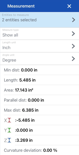
The Onshape Measure tool is available in Part Studios for sketches and parts, and in Assemblies for parts and assemblies; it appears in the far right of the main toolbar at the top of the screen. It displays measurement dynamically whenever you select an entity. The tool shows all possible measurements for the selected entity/entities including, but not limited to, minimum distance between entities, total surface area, angles, length, parallel distance, etc.
Steps
The Measure tool displays measurements dynamically whenever you select entities.
- Tap the Measure tool
to active it.
With the Measure tool active:
- Tap to select an entity (or entities) to measure.
The relevant measurement information appears in the dialog at the bottom of the screen. Tap the top of the dialog to collapse or expand it. Swipe inside the dialog to scroll up or down.
-
Use the dropdowns to specify Measure type, Length unit, and Angle unit (these can be changed at any time).
- Tap the X in the upper right corner of the Measure dialog to close it and exit the measurement tool.
The measurement tool displays information using the units of measurement that you have set for your document. To change the units of measurement, select Units from the document info panel and select desired unit.