Variable Studio Configurations
![]()
![]()
iOS support for Variable Studio configurations is limited to viewing and using configurations that are created on the desktop (browser) platform only.
Available in: Variable Studio
In Onshape, you can configure Variable Studios similar to the way you can configure Part Studios and Assemblies. The configuration inputs you define in a Variable Studio become options in the Insert dialog when you insert the Variable Studio into another tab or document.
See also:
-
Managing Configurations (including renaming, filtering, copy/pasting, and more)
-
Visibility Conditions (configuration logic)
- Click the
 icon on the right side of the Variable Studio window to open the Configuration panel.
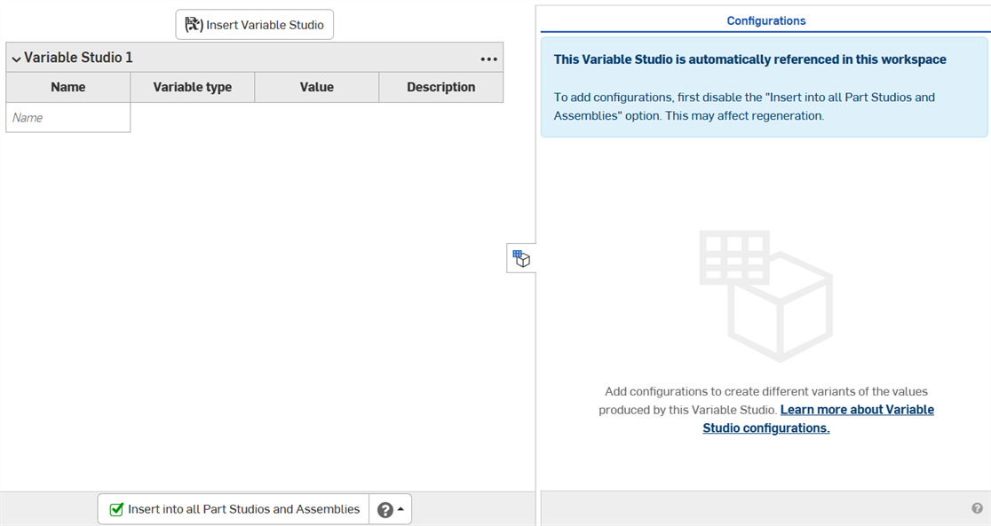
- The Variable Studio cannot be configured while being automatically referenced. Deselect the Insert into all Part Studios and Assemblies checkbox. (When you insert a configured variable table into a Part Studio or assembly, you must choose which configurations to insert.)
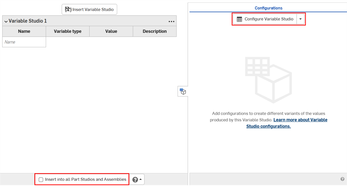
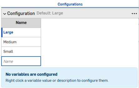
- Click Configure Variable Studio. A configuration input table appears in the Configuration panel.
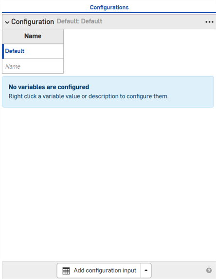
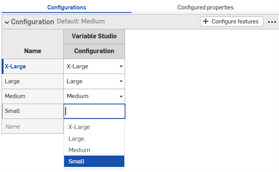
- Click in the first row to activate it, and enter the input value names in the first column. Press Tab to move to the next row. The blue bar to the left of the row indicates the currently selected configuration in the Variable Studio.
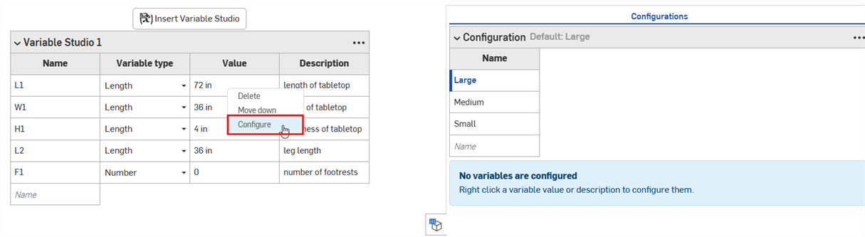
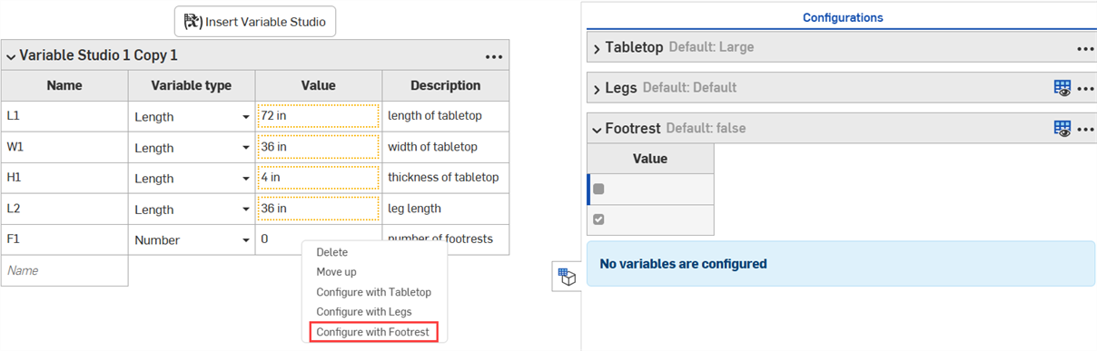
- Right-click a variable value or description and click Configure on the context menu to add it to the configuration table.
- Continue right-clicking and selecting Configure to add additional values or descriptions to the table. The selections are added to the table with their default values, and are highlighted in orange in the Variable Studio.
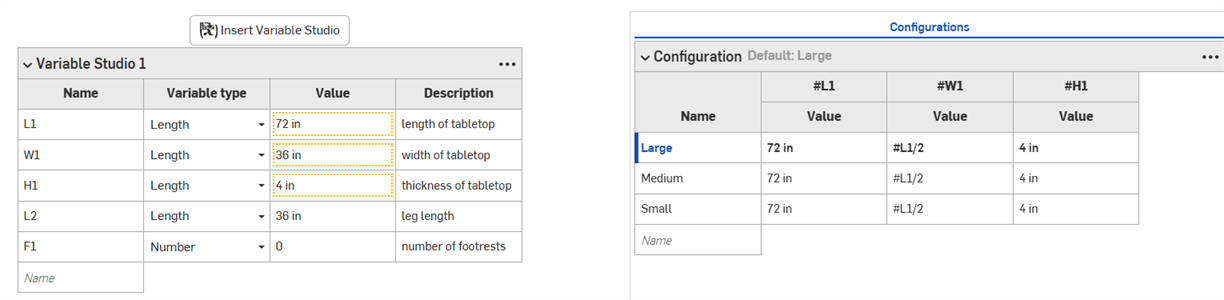
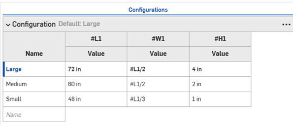
- Double-click and edit the values in the configuration table as necessary.
-
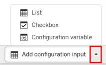
To add additional list inputs, click the Add configuration input arrow at the bottom of the Configuration panel and select List.
-
To remove a value or description from a configuration, right-click it in the Variable Studio and click Unconfigure or Unconfigure from.
- At the bottom of the Configuration panel, click the Add configuration input arrow and select Checkbox.
- Add a Name for the input in the dialog that appears.
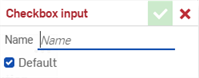
- Use the Default option to specify if the configuration should be checked or unchecked by default. This can be changed later.
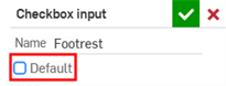
- Click the green check mark to add the input to the Configuration panel.
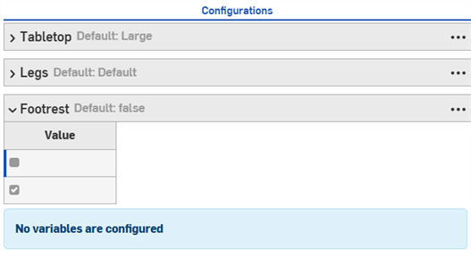
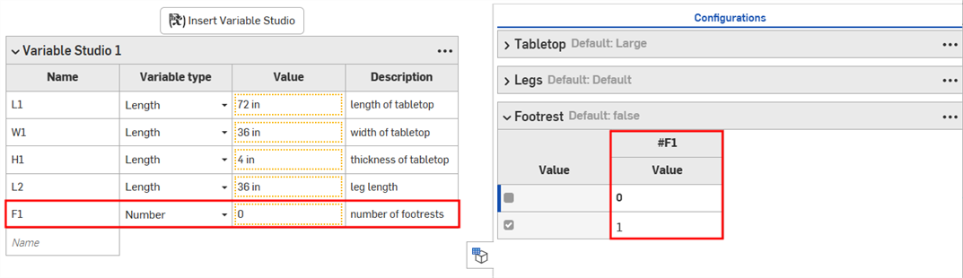
- Right-click the value or description to configure in the Variable Studio, and click Configure with to add the value to the input.
- Edit the values in the input as needed.
- Click the Add configuration input arrow and select Configuration variable.
- Add a Name for the variable in the dialog that appears.
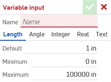
- Select a type for the variable. Choose from Length, Angle, Integer, Real, or Text.
- Enter the values for the variable.
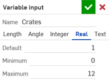
- Click the green check mark to add the input to the Configuration panel.
- Enter the values for the variable.
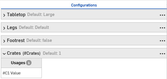
- Right-click a value or description in the Variable Studio and select Set to...
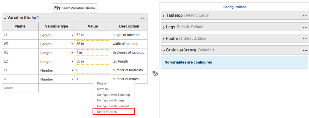
The value is added to the Configuration panel
Configured Variable Studios cannot be released.
-
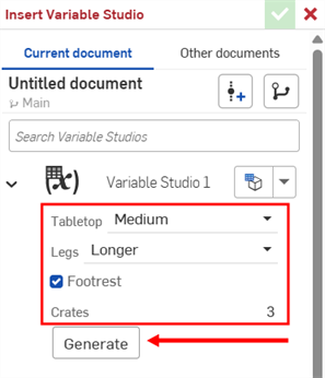
In the Insert Variable Studio dialog, select the configured Variable Studio.
-
Make selections in the dialog to specify which configurations you want, then click Generate.
Click the Set to last viewed configuration dropdown (
 ) to select the last active configuration in the Variable Studio, or select Reset to default to set all inputs to their default values.
 -
Click the Variable Studio to insert it into your Variable table, or select individual variables from the generated list.
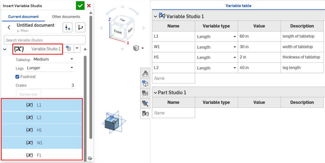
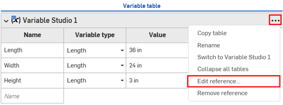
- Insert the configured Variable Studio into the Variable table as described in the last section.
- In the Variable table, click the three-dot menu button and select Edit reference.
- In the Update Variable Studio dialog, right-click the configuration and select Configure (or Configure with if multiple configuration inputs exist in the Part Studio or assembly).
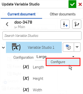
- A notification appears that the Variable Studio has been added to the Part Studio/Assembly configuration. Click the checkmark to close the dialog.
- Open the Configuration panel in the Part Studio or assembly. The Variable Studio configuration becomes a feature (column) in the Configuration panel.