 Geometric Tolerance

Available in: Drawing
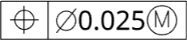
Often associated with datum, use Geometric tolerance to create and place basic dimension notations in the drawing, like this:

 Video example: Datums and geometric tolerances
Video transcript
Datums and Geometric tolerances are an integral part of communicating manufacturing variation within a drawing.
Add a Datum to the drawing. Stay in the Datum tab to quickly place datums along drawing view edges. The Label field automatically populates with a letter, but it is customizable. Click a view edge to attach the Datum symbol with a leader. Click again to place it. The tool stays active for continuous placement of additional symbols.
Click the Datum target tab to define a specific area to apply another datum. In the Target area dropdown, select a shape. In the Style dropdown, select a callout. Check Area size to specify the target shape. A diameter defines the size of an X, Point, or Circle, while the size of a Rectangle is defined by side lengths. Select the precision from the dropdown. Enter a value for Diameter. Click a view location to attach the symbol. Click again to place it.
Accept the dialog or choose to add dimensions using Targets. Use the Origin target location when there is a vertex where the X and Y axis intersects, or define the X and Y directions by selecting edges in the view. Click the X and Y opposite direction arrows to flip the dimension placement. Accept the Datum.
Reposition by selecting the grip points at the base or dragging the end. Edit from its right-click context menu or double left-click.
Add a Geometric tolerance. Select the tolerance Symbol, enter the tolerance, and input any needed Datums. Insert a Leader, add Symbols, and add Geometric tolerance modifiers such as maximum material condition. Select any combination of Free state, Tangent plane, or Projected tolerance zone.
Add additional frames by clicking the Add frames icon. Successive frames provide a new option in the Symbols dropdown for Composite. This spans the Symbol across both frames. Remove extra frames by clicking the Remove last frame icon.
Click anywhere on the sheet or click a dimension to place the Geometric tolerance. Continue placing additional Geometric tolerances or accept the dialog. When placed on a dimension, it is snapped to the dimension, following it when moved. Drag a Geometric tolerance off a dimension to unsnap it. Drag it on a dimension to snap it.
Edit a Geometric tolerance from its right-click context menu or double left-click to open the edit dialog.
Creating a tolerance
Tolerances can be attached to edges, holes, dimensions (with or without leaders), dimension extension lines, extension lines, surface regions, and even away from an edge (with no leader).
Creating a tolerance:
-
Click
 .
.
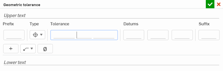
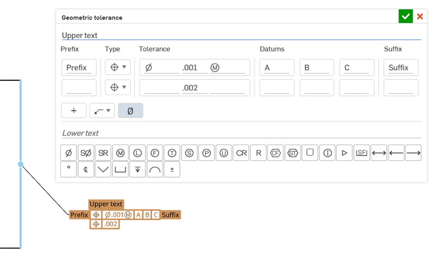
- In the dialog, from corresponding lists, specify the symbols and associated tolerances for your drawing:
- Complete the specifications by entering the following information:
Upper/Lower text field - Add information above or below the Geometric tolerance. The Upper text field allows up to 50 characters. The Lower text field allows up to 200 characters.
Prefix/Suffix - Enter a Prefix or Suffix to add information to the left or right of the Geometric tolerance frame, respectively. Both fields allow up to 20 characters.
Tolerance frame
- Symbol (Geometric tolerance type) - Select the type of Geometric tolerance from this dropdown field. The symbol is placed to the left of the Geometric tolerance. Options are: Position, Concentricity, Symmetry, Parallelism, Perpendicularity, Angularity, Cylindricity, Flatness, Roundness, Straightness, Profile (Surface), Profile (Line), Circular runout, and Total runout.
- Tolerance - Enter a tolerance value. Optionally, enter symbols in fields to the left and/or right of the tolerance value. Both left/right fields allow up to 7 symbols. Non-allowable symbols can be added here and are accepted, but not recommended.
- Datums - Enter up to 3 datum values in the 3 Datum fields. Each field must start with at least one uppercase letter, and then symbols can be added in using the Symbols palette (see Show/Hide symbols below). Hyphens are also accepted in this field.
- Add frame - Click the Add frame icon (
 )
to add an additional constraint row to the table. Up to 5 constraints can be added to the Geometric tolerance. Change the bottom symbol to Composite to create a composite frame.
)
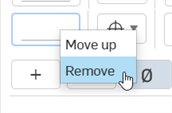
to add an additional constraint row to the table. Up to 5 constraints can be added to the Geometric tolerance. Change the bottom symbol to Composite to create a composite frame.To move or remove a constraint line, right-click anywhere on the cells in that line and select either Move up/down (to move the constraint up/down one row in the table) or Remove (to remove the constraint row from the table). This can only be performed on additional constraint rows.
Leader - Click the Leader icon dropdown and select Leader (
 ), All around (
 ), or All over (
 ).
).- Show/Hide symbols - Click the Show symbols icon (ø) to open a table of symbols that can be inserted into the Geometric tolerance fields. When in the Upper/Lower text and Prefix/Suffix fields, all symbols are available:
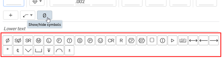
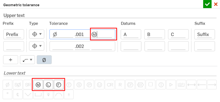
If you are in a field inside the Tolerance frame, the combination of Geometric symbol type and a particular field determines the symbols available for use. For example, in the field after the Tolerance value, the following symbol options are available:
- Click in the graphics area to place the tolerance.
To place tolerance with a leader, hover over drawing view until a snap point appears, click with the desired snap point visible, drag tolerance and click to place. To add another leader, right-click the leader and select Add leader. Click to place additional leader. Repeat to add more leaders:
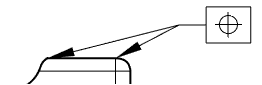
The leader includes a moveable node along the horizontal segment:
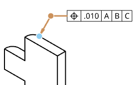
Click and drag the node to extend or shrink the horizontal segment of the leader line.
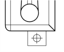
To place the tolerance on an edge in the view, place the tolerance first, then drag it to the edge and release when there is no leader visible:
To place the tolerance along an extension line, drag the tolerance away from the snap point, until an extension line appears: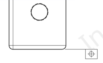
To place the tolerance on a surface region, click at the surface location and drag the tolerance to the desired location:
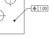
You can also place tolerances on centermarks as well as manually placed centermarks.
When aligning dimensions and annotations, you can hover over edges, midpoints, or other lines to activate red inference points. Use the inference points to snap the location of the entity when creating or dragging a dimension or annotation. Similarly, you can move the mouse vertically or horizontally over views, lines, dimensions, or annotations to activate pink vertical and horizontal inference lines. Use these inference lines to align the location of the entity vertically or horizontally from the desired referenced annotation.
The tolerance displays in the graphics area.
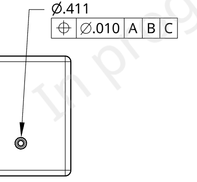
Tolerance with leader:
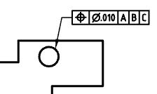
You can drag a geometric tolerance closer to or farther away from its placement point on the drawing, and the extension line adjusts appropriately. You also have the ability to attach and orient the geometric tolerance to other drawing annotations.
When dragging away from a dimension, the geometric tolerance automatically gains a leader and remains inline with the dimension.
Grouping tolerances
Grouping a tolerance to an annotation
To group a tolerance to an annotation, for example, a dimension or hole callout:
-
Click to select the tolerance.
-
Drag the tolerance to an existing dimension. When the dimension gains a highlight, release the drag.
To group a tolerance during creation:
- Once the tolerance dialog is open, make your necessary changes in the dialog.
- When placing the tolerance in the drawing area, click on the dimension you wish to group it with.
When you move a tolerance, the tolerance is ungrouped.
To move them both together, click and drag the dimension to the new location. To move the tolerance, click and drag it to a new location.
Moving the tolerance breaks the group connection between it and the dimension. To regroup it, drag and drop the tolerance on the dimension.
Grouping a tolerance to a callout group
To group a tolerance to a dimension that has a grouped callout, for an example, a dimension with a balloon callout grouped with it:
- Click to select the tolerance.
- Drag the tolerance to the existing dimension. When the dimension gains a highlight, release the drag.
To group a tolerance during creation:
- Once the tolerance dialog is open, make your necessary changes in the dialog.
- When placing the tolerance in the drawing area, click on the dimension.
To move the callout group together, click and drag the dimension to the new location. Alternately, click on the tolerance or callout to select it. Then click anywhere outside the grip point (shown by the cursor below) to move the entities together to a new location.
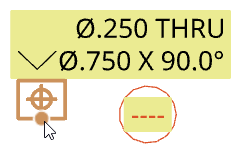
To move the tolerance without moving the group, click to select it. Then click its grip point and move it to a new location. The tolerance remains part of the callout group, even after it is moved to the new location.
Editing a tolerance
To edit a tolerance:
- Double-click on the tolerance in the graphics area.
- Make your changes in the dialog that opens.
Styling tolerances
To style a tolerance:
-
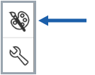
Click on the tolerance you want to style, then click the Styles panel icon on the right side of the page:
-
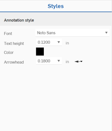
Edit the Font, Text height, Color, and Arrowhead:
Add/remove leader nodes
- Right-click on the leader and click Add node:
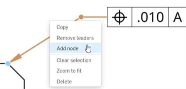
A node will appear on the leader. To add another node, right click on the leader and select Add node again.
- To remove a node from a leader, right click on the node and select Remove node.
- You are also able to add leaders to nodes by right clicking on the node and selecting Add leader. This will add a leader starting from that node and ending wherever you click next.
Geometric tolerance context menu
Right-click the geometric tolerance symbol to open the context menu:
- Edit - Open the geometric tolerance dialog to edit the geometric tolerance specifications.
- Paste - Paste the copied geometric tolerance.
- Copy - Copy the geometric tolerance.
- Paste as table - Paste the copied geometric tolerance as a table format.
- Add leader - Add a leader (or another leader) to the geometric tolerance symbol.
- Remove leaders - Remove all leaders from the geometric tolerance symbol.
- Move to - Move a geometric tolerance symbol to a different layer of the drawing: Border frame, Border zones, or Title block. Once on another zone, you have the option of locking the layers (through Drawings properties, Formats tab), in order to stabilize the position of entities on that layer. When a geometric tolerance is moved to different layer, that layer's formats (for example, color, line thickness, and font) are applied to it.
- Clear selection - Remove any highlighted items from the selection queue.
- Zoom to fit - Zoom appropriately to fit the entire drawing in the field of view.
- Delete - Delete selected entities.
Symbols
Geometric characteristic symbols
| Symbol | Characteristics | Type |

|
Position | Location |

|
Concentricity or coaxiality | Location |

|
Symmetry | Location |

|
Parallelism | Orientation |

|
Perpendicularity | Orientation |

|
Angularity | Orientation |

|
Cylindricity | Form |

|
Flatness | Form |

|
Circularity or roundness | Form |

|
Straightness | Form |

|
Square | Form |

|
Profile of a surface | Profile |

|
Profile of a line | Profile |

|
Circular runout | Runout |

|
Total runout | Runout |
Leader symbols
| Symbol | Characteristics |
|
|
Leader |
|
|
All around |
|
|
All over |
Diameter symbols
| Symbol | Characteristics |
| Ø | Diameter |
| SØ | Spherical diameter |
| R | Radius |
| SR | Spherical radius |
| CR | Controlled radius |
Modifier symbols
| Symbol | Characteristics | Type |

|
At maximum material condition, a feature contains the maximum amount of material stated in the limits | MMC |

|
At least material condition, a feature contains the minimum amount of material stated in the limits. | LMC |

|
Regardless of feature size, indicates that the feature can be any size within the state limits. | RFS |

|
Free state | F |

|
Tangent plane | T |

|
Unequally disposed profile/Unilateral tolerance. Specifies the amount of material out of the total tolerance that is added to the part. | |
| ℗ | Projected tolerance zone | |

|
Statistical tolerance. Indicates tolerances to related assembly components based on sound statistics. | |

|
Continuous feature. Indicates when two or more interrupted features should be treated as a single feature | |

|
Spot face. Indicates the surface to be spot faced. | |

|
Translation. Indicates that a datum feature simulator is not fixed at its basic location and shall be free to translate. |