

Available in: Drawing
Place an edge condition symbol on a Drawing, also known as an edge break symbol, to show the acceptable state of a corner created during machining.
 Steps
- Click the Edge condition symbol icon (
 ).
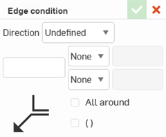
- In the Edge condition dialog, set the following:
Click the Direction dropdown to select Undefined, Vertical, Horizontal, or Asymmetric.
Optionally, enter a quantity or notes in the text field.
By default, each of the two deviations are set to None. Optionally, select a +, -, or ± sign and enter a value.
Optionally, select the All around checkbox to include an all around symbol.
Optionally, check the Parentheses checkbox to add it to the symbol.
- Click a vertex or an edge in a view to place the arrow.
- Click again to place the symbol.
-
Click the checkmark (
 ) to accept the Edge condition.
To edit an Edge condition symbol, double-click it, or right-click it and select Edit.
Styling edge condition symbols
To style an Edge condition symbol:
-
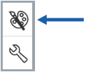
Click the Edge condition symbol, then click the Styles panel icon on the right side of the page:
-
Edit the symbol style properties, such as Font, Text height, Color, and Arrowhead.
Edge condition symbol context menu
Right-click the edge condition symbol to open the context menu:
- Edit - Open the Edge condition dialog to edit the symbol
- Paste - Pastes the symbol
- Copy - Copies the symbol
- Paste as table - Pastes clipboard content as a table at the current location
- Add leader - Adds the symbol leader line
- Remove leaders - Removes the symbol leader lines
- Move to - Moves the symbol to the Border frame, Border zones, Title block, or Drawing.
- Add comment - Adds a comment to the symbol
- Clear selection - Deselects the symbol
- Zoom to fit - Zooms in to fit on-screen
- Delete - Delete selected entities