 Drawing Flat Pattern View
![]()
![]()
![]()
Available in: Drawing
A sheet metal flat pattern view can only be inserted from the Insert dialog. Once inserted from this dialog it can be placed into the sheet.
Flat patterns display the following in the drawing:
-
Bend line default line thickness and color for up and down bend lines:
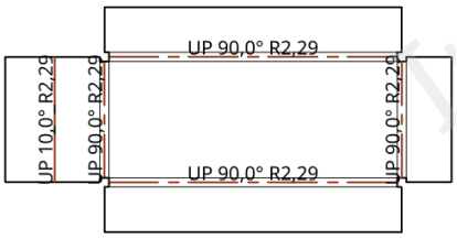
In the illustration above, all bend lines have a value of 0.50mm and the up bend lines have a red color specified
-
Form outline where the sheet metal is cut.
-
Form outline on the sheet metal's top and bottom surfaces.
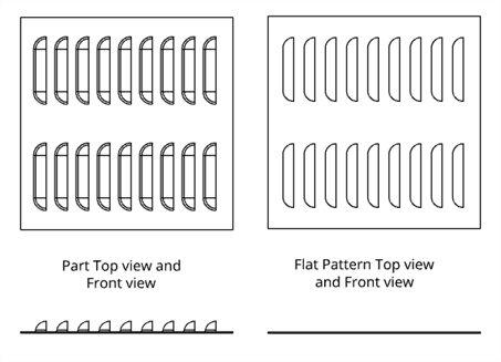
Form outlines displayed in the flat pattern.
-
Form sheet metal centermarks
-
Large diameter of counterbore and countersink holes on the sheet metal's top and bottom surfaces.
See Flat pattern views for ways in which you can adjust the drawing's flat pattern view properties.
Refer to the Sheet Metal Table and Flat View and Form topics for more information.
This table illustrates the types of views from which the Flat pattern view can be created:
| Flat pattern view | |
| Can be created from: | Cannot be created from: |
|
Insert view dialog |
Any views |