Rigid Body


Only available for
Available in: Assembly
Select bodies to be included in the Simulation while remaining non-deformable.
Onshape Simulation’s Rigid body feature gives users the ability to treat any part instance as a rigid solid body. This designation is not to be confused with a “rigid body element” (for example, RBE2 or RBE3), which introduces an entirely new and non-physical or abstract body to the Assembly. Instead, the Rigid body feature in Onshape acts on an already existing and physical or real part Instance in an Assembly.
The Rigid body feature has no effect outside Simulation. In the context of a Simulation, any designated Instance does not experience any internal deformation, though it may still experience rigid body translations and rotations. The rigid body feature makes a Part Instance infinitely strong.
The ability to designate objects as rigid is common across finite element analysis; in many ways, it is a more foundational element than the deformable finite elements available in Onshape Simulation today. Users enjoy the Rigid body feature for one of two intended use cases:
-
Modeling objects that intentionally represent infinite strength and stiffness. This is useful when comparing analysis results against handbook calculations or book-ending a physical scenario with worst-case conditions.
-
Simplifying the computational complexity of the system. This is useful when the part instances that are made rigid are significantly stronger than the part instances with which they interface and/or whose detailed analysis is of little to no interest to the greater Assembly.
The most common example, which supports both cases, is one in which a user wants to represent all fasteners in an assembly as rigid bodies. This ensures the entire stress of the load is borne by the components to be fastened (thus representing a worst-case scenario) and significantly simplifies the simulation model (by demanding little to no computational expense for the multitude of fasteners).
Rigid body part instances are excluded from the 100 part instance limitation for a simulation run. Using a Rigid body feature is a way to avoid that limitation.
 Selection rules
-
Only part instances can be selected. Faces, surfaces, or composite parts cannot be selected.
-
A user can create multiple Rigid body features, and the same part instance can appear in more than one such feature.
-
If a part Instance is referenced by more than one unsuppressed Rigid body feature, there is no additional rigidity that affects the simulation. Rigidity is not cumulative.
-
Multiple part instances can be selected in a single feature.
-
If a part Instance is both rigid and fixed, its fixed state takes precedence over it's rigid state.
Material property requirements
-
Since a simulation requires a material assignment to every non-fixed part before it can run, rigid part instances inherit this requirement.
-
Linear static analysis - Material properties are not required for a rigid part Instance, unless the part is also loaded with inertial or body-force calculations (not to be confused with a Force load feature applied to a part instance). When the rigid part instance is directly loaded with an Acceleration or Angular velocity load feature, or the Linear static simulation includes inertial relief, then the rigid part instance must have Density defined.
-
Modal analysis - Density is the only Material property required for a rigid part Instance. Mass properties are still required for modal frequency calculations.
-
Rigid bodies do not require stiffness-related properties, such as Young's modulus or Poisson's ratio, since they do not deform. Mass-related properties, such as Density, is required when inertial loads are involved.
Steps
This workflow assumes you have a completed CAD model in an Assembly tab, with the instances mated and the assembly sufficiently constrained, and a simulation properly defined:
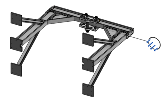
-
Click on the Rigid body icon (
 ).
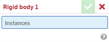
-
Select any instances that should remain non-deformable from either the instances list or graphics area. Ensure they meet the Selection rules and Material property requirements.
Once an instance is added to the list, a Rigid body glyph (
) is added to the graphics area, A leader line connects the glyph to the first instance in the dialog (see below).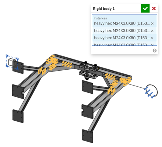
-
Click the checkmark to accept the new Rigid body feature (
 ).
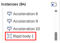
The feature appears in the Assembly's instances list:
-
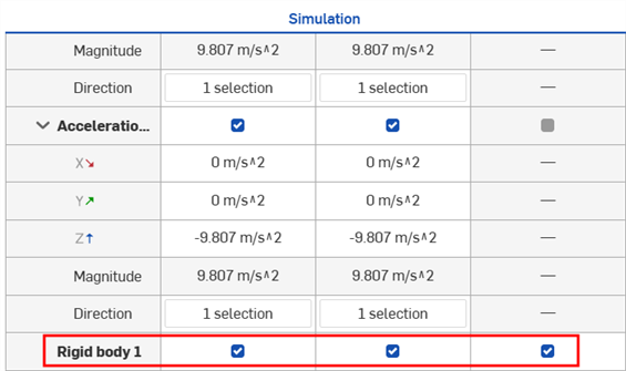
The Rigid body feature can be suppressed on a per-simulation basis in the Simulation table (see below), or by right-clicking on the feature in the Instances list and selecting Suppress. However, the set of parts in a given feature cannot vary across simulations.
-
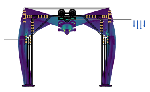
Run the Simulation with the Rigid body feature enabled. The final results are shown below for our example model: