 Assembly Circular Pattern
![]()
![]()
![]()
Available in: Assembly
Pattern selected entities about an axis. For information on creating linear patterns, see Assembly Linear Pattern.
- Click
 .
.
- With the focus in the Instances field, select instances (part, subassembly, sketch or surface) to pattern. Click to select an entity from the workspace or from the Instances list.
- Set focus in the Axis of pattern field, and then select an edge, face, mate connector (implicit or explicit), or conic or cylindrical face of the entity about which to place the pattern.
To select implicit mate connectors, click . Once a mate connector is selected, click the Mate connector icon in the dialog field (outlined in blue below) to open the Mate connector dialog, and make edits as needed:
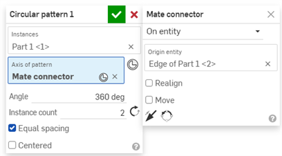
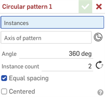
- In the Angle field, enter the distance (in degrees) between pattern instances.
- In the Instance count field, set the number of instances for your pattern. The minimum number of instances you are able to use is 1.
- Click the opposite arrow icon to change the direction of the pattern.
- Click to set equal spacing.
-
Click
 .
.
- If you create a pattern of an entity that is in a group, the new instances are also in that group. For more information on groups, see Group.
- Patterned subassembly components and mates are not rigid; you can move individual components without suppressing the pattern, and positional changes will be reflected in the other subassembly instances.
- If a seed instance is suppressed, all assembly pattern instances become inactive.
- Assembly patterns can be moved to subassemblies just like parts. See Move to subassembly for details.