Create a slot feature in FeatureScript
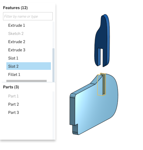
In this series of tutorials, we will create a slot feature, designed for joining two laser-cut parts. Eventually, we will use this feature to make large assemblies of laser-cuttable parts which are joined with slot features.
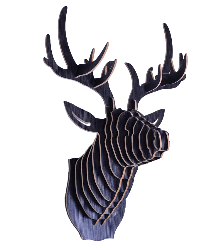
The slot feature is just one example of what FeatureScript can do, but each tutorial in the series introduces concepts which can be applied to a wide variety of features.
In the first tutorial, we'll walk through how to:
- Create a new "Slot" feature type
- Specify the feature's inputs
- Define the feature's behavior
- Use instances of the feature in a Part Studio
Motivation
A slot is simple to create with or without using FeatureScript. However, encapsulating the behavior in a custom feature provides some key advantages:
Interface control: With FeatureScript, we can fully specify the feature dialog interface, and optimize the workflow. In this tutorial, our feature's input will include the sketched path, but in future tutorials, we improve this interface so that we can create a pair of slots with just two selections.
Update everywhere: Each instance of a "Slot" feature points to the same feature definition, so each time we improve our slot feature, every instance in the document is immediately updated. When using features from a different document, a user can update by repointing their document to any published version of the feature.
Error handling: When invalid inputs are entered, errors can be reported to help diagnose what's wrong. With this workflow, the end user will immediately see if they've made a slot that won't fit, or won't laser cut: reported errors will turn a feature red in the feature tree.
Quality assurance: Your features will have more knowledge about their purpose than generic Onshape features, so their specific edge cases can be handled better. This, in combination with error handling, can mean the end user is less likely to make mistakes.
Video overview
This video shows the creation of the slot feature. It demonstrates what a FeatureScript workflow can look like, and creates the same "Slot" feature type that the tutorial will guide you through below.
Step-by-step guide
This guide will take you step by step through the actions shown in the video above, explaining what the FeatureScript does and why. Major FeatureScript concepts will be marked in bold when they are explained.
READING FEATURESCRIPT TUTORIALS
In this and all other FeatureScript tutorials, changes to the code will always be mentioned in code blocks, like those below. The surrounding instructions will tell you about that code and what to do with it. In addition, the code block's color gives an indication about what action needs to be taken:
Green indicates that this code should be inserted into the Feature Studio.
Red indicates that this code should be deleted from the Feature Studio.
Yellow indicates that this code should be changed. The newly changed code is highlighted.
Blue indicates that this code is unchanged or final.
Create a feature definition
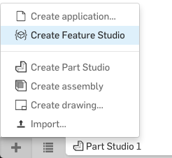
Start by creating a new Feature Studio tab in a new Onshape document:
A Feature Studio is a place for editing FeatureScript where you can define functions to be used as feature types. All of Onshape's native feature types, from extrude to helix, are also written as FeatureScript feature types in the Onshape Standard Library. Custom feature types that you write here will be treated like Onshape feature types in the Part Studio.
In the Feature Studio, in the top-left corner, click the "New feature" button.
This will insert the following code, which is the minimum template for defining an empty feature type:
annotation { "Feature Type Name" : "My Feature" }
export const myFeature = defineFeature(function(context is Context, id is Id, definition is map)
    precondition
    {
        // Define the parameters of the feature type
    }
    {
        // Define the function's action
    });
For more information about the structure and pieces of a feature definition, see Writing features.
NOTE
In the Feature Studio, the code inserted by the "New feature" button has several sections of text marked as **autocomplete regions**. If you look closely, you can identify these regions by a thin, gray box outline:
Autocomplete regions are temporary navigation aids designed to help you write features quickly, and generally indicate the regions of inserted text that you are likely to change. You can navigate your cursor through these regions using the following keyboard shortcuts:
- tab : Select next autocomplete region
- shift-tab : Select previous autocomplete region
- escape : Dismiss all autocomplete regions
Moving your cursor outside a region (with the mouse or arrow keys) will also dismiss all autocomplete regions.
After pressing the "New feature" button, you should see the text
"My Feature"highlighted. This field is astringwhich defines the user-visible name of the feature type. This name is seen when a user inserts the feature, and in default feature names (e.g. "Extrude 1"). The feature type name can include whitespace, and can be changed at any time without affecting Part Studios' behavior or other FeatureScript code.Change the feature type name to
"Slot":annotation { "Feature Type Name" : "Slot" }Select the text
myFeatureon the next line (with autocomplete regions, you can presstabto select the next field). This is the FeatureScript name of this feature function. The function name is used by any FeatureScript calls that create this feature, including features created in the Part Studio. Thus, changing this name after creating features will break all features created with the old name. This name cannot include whitespace or special characters.Change the FeatureScript function name to "
slot":export const slot = defineFeature(function(context is Context, id is Id, definition is map)
Your Feature Studio should now look like this (but with a different FeatureScript version and import version):
FeatureScript 1890;
import(path : "onshape/std/common.fs", version : "1890.0");

annotation { "Feature Type Name" : "Slot" }
export const slot = defineFeature(function(context is Context, id is Id, definition is map)
    precondition
    {
        // Define the parameters of the feature type
    }
    {
        // Define the function's action
    });
Define the feature's input parameters
Select the next region: "
// Define the parameters of the feature type". This section of code, between the two curly braces, is the function's precondition. The precondition is used, in part, to define a feature's input parameters. The text highlighted is a comment, which does not affect FeatureScript evaluation.Delete this comment:
// Define the parameters of the feature type
Our feature's first input parameter will be an edge which defines the slot path. Input parameters to features are stored in its
definition: amapwhose keys are strings. These parameters can later be accessed from thedefinitionto define how the feature should be built.All geometry in FeatureScript is passed into features as Queries, so we will define a query parameter.
Start typing "query". The autocompletion menu will expand below your cursor as you type. One of the autocompletions you should be able to see is "Query parameter", a snippet of code which, when placed in a feature precondition, defines a query parameter.
NOTE
Typing in a Feature Studio will often bring up a context-sensitive **autocomplete menu**. This menu shows a list of one or more autocompletions which match what you're typing: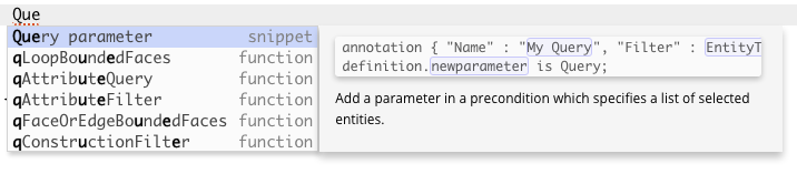
The flyout on the right side shows a preview of the text you will autocomplete, along with a short description. Autocomplete will show FeatureScript functions (including features), types, enums, and snippets (i.e. short FeatureScript code templates).
When an autocompletion menu is open, you can use the following shortcuts to navigate the menu:
- up/down arrow keys : Select next/previous item in menu
- enter : Insert selected autocompletion
- escape : Remove the autocompletion menu
The second parameter will define the part to cut. Since this parameter will also take in model geometry, we will use another query parameter.
On the line after the slot path parameter, start typing "query", and select the autocompletion for "Query parameter":
annotation { "Name" : "My Query", "Filter" : EntityType.FACE, "MaxNumberOfPicks" : 1 } definition.parameter is Query;Fill out its fields with the following:
annotation { "Name" : "Part to cut", "Filter" : EntityType.BODY && BodyType.SOLID, "MaxNumberOfPicks" : 1 } definition.partToCut is Query;NOTE
The filter above specifies that a user can select any full part in the Part Studio to use for this parameter.Any selectable piece of topology in Onshape (edges, vertices, parts, etc.) is known as an entity. Every entity has an EntityType and a BodyType which specify what kind of geometry it represents.
The EntityType
BODYspecifies a full, independent object in the Part Studio. ABODYis often a part, but it can also be things of lower dimension. The dimension of a body is distinguished by its BodyType:BodyType.SOLID, as in the filter above, specifies an independent three-dimensional part (such as the result of extruding a sketch region)BodyType.SHEETspecifies an independent two-dimensional surface (such as the default planes, or the result of extruding a sketch edge)BodyType.WIREspecifies an independent one-dimensional path (such as the result of a helix feature)BodyType.POINTspecifies a independent zero-dimensional point (such as the origin, or the result of opPoint)
Entities which are not
EntityType.BODY, like a single face of a part, are always children of some other entity. The otherEntityTypes specify child entities of a certain dimension:EntityType.FACEspecifies a two-dimensional childEntityType.EDGEspecifies a one-dimensional childEntityType.VERTEXspecifies a zero-dimensional child
A child entity will have a
BodyTypewhich matches dimension of its owner body.For more information on combining these and other filters, refer to the documentation on query parameters.
The final feature parameter will define the width of the slot. Since this parameter is a one-dimensional distance, we will use a length parameter.
On the line after the slot path parameter, start typing "length", and select the autocompletion for "Length parameter":
annotation { "Name" : "My Length" } isLength(definition.parameter, LENGTH_BOUNDS);Fill out its fields to name the parameter:
annotation { "Name" : "Width" } isLength(definition.width, LENGTH_BOUNDS);Add blank lines between the parameters for code readability. Your final precondition should now look as follows:
precondition { annotation { "Name" : "Slot path", "Filter" : EntityType.EDGE, "MaxNumberOfPicks" : 1 } definition.slotPath is Query; annotation { "Name" : "Part to cut", "Filter" : EntityType.BODY && BodyType.SOLID, "MaxNumberOfPicks" : 1 } definition.partToCut is Query; annotation { "Name" : "Width" } isLength(definition.width, LENGTH_BOUNDS); }NOTE
FeatureScript is a whitespace insensitive language. This means that, as long as you aren't breaking up individual words or strings, you can insert or remove spaces and newlines anywhere without affecting the meaning.At this point, your Feature Studio should be free of errors. You can determine this by looking at the FeatureScript notices indicator on the right side of the top navbar. If there are no errors, this icon will be gray. If there are only warnings, it will be yellow. If there are errors, it will be red:


Use the arrow keys (if necessary) to select the "Query parameter" snippet, and press enter to insert the autocompletion. This will insert the following code:
annotation { "Name" : "My Query", "Filter" : EntityType.FACE, "MaxNumberOfPicks" : 1 }
definition.parameter is Query;
NOTE
The code above represents a feature **parameter**, which the user will pass into the feature, and FeatureScript code will use. The parameter is defined on the second line, which asserts that the field "`parameter`" on the definition is a `Query` for geometry.The first line is an annotation, associated with the line that defines the parameter. The information in this annotation indicates how Onshape should create an entry for this parameter in the feature dialog.
After inserting the Query parameter autocompletion, you should see the text "My Query" highlighted. This is the user-visible name of the parameter. Query parameter names are visible in the feature dialog when the field is empty.
Change the user-visible parameter name to "Slot path":
annotation { "Name" : "Slot path", "Filter" : EntityType.FACE, "MaxNumberOfPicks" : 1 }
definition.parameter is Query;
Select the next region: "EntityType.FACE". This field represents a filter that controls which geometric entities can be accepted by the parameter. You can filter by EntityType, GeometryType, BodyType, and more.
To allow only edges, change the filter to "EntityType.EDGE":
annotation { "Name" : "Slot path", "Filter" : EntityType.EDGE, "MaxNumberOfPicks" : 1 }
definition.parameter is Query;
Select the next region: "1". This field represents the maximum number of selections the user can make in this field. This field can also be removed to allow infinite selections.
To allow just one edge selection, leave the default of 1:
annotation { "Name" : "Slot path", "Filter" : EntityType.EDGE, "MaxNumberOfPicks" : 1 }
definition.parameter is Query;
Select the next region: "parameter". This is the FeatureScript-visible name of this parameter, which will later be used to access this parameter within the function's body. The value of this parameter is stored as a Query on a map named "definition".
Change the FeatureScript parameter name to "slotPath":
annotation { "Name" : "Slot path", "Filter" : EntityType.FACE, "MaxNumberOfPicks" : 1 }
definition.slotPath is Query;
Create an instance of your feature
To commit the changes you've made to your Feature Studio, press the "Commit" button in the FeatureScript toolbar:

NOTE
The FeatureScript you write is always being saved in the cloud, just like other Onshape tabs. However, because code is usually not sensible as it's being typed, FeatureScript changes are not immediately visible to *other* tabs. For this, you will need to **commit** your changes.You can think of "commit" as "Update the whole document with these changes". Once changes to a Feature Studio are committed, Part Studios which depend on that Feature Studio will regenerate when you switch to them. If this causes run-time errors, those errors will appear in the FeatureScript notices flyout at this point.
If you have changed a Feature Studio but not committed, you will see an asterisk before the element name on the Feature Studio tab, indicating the presence of uncommited changes:
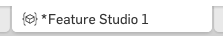
If you close a browser tab with uncommitted changes, nothing is lost. You'll still see these uncommitted changes in the Feature Studio when you return.
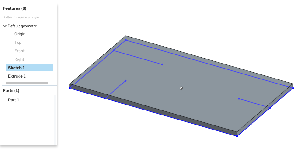
Switch to Part Studio 1. In this Part Studio, make some geometry that the slot feature can be tested on. Create a sketch with internal, perpendicular edges, like the one below, and extrude it:
You should see a new icon in the toolbar for your new custom "Slot" feature. This dropdown menu will show all the custom feature types defined in this workspace.
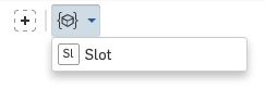
The name "Slot" seen here comes from the "Feature Type Name" you defined in the Feature Studio earlier. The icon for the feature is created automatically with the first two letter of that name.
Click the Slot feature button. This will pull up a feature dialog for your feature. If your precondition is written correctly, this feature dialog should look like this:
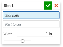
As input to your feature, choose an internal edge for the slot, choose the extruded part as the part to cut, and set the width to "3mm".
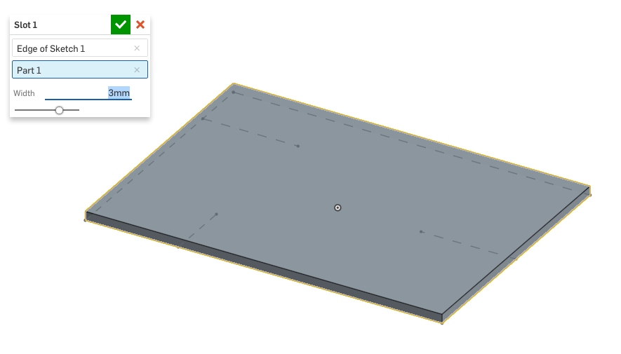
NOTE
When selecting the slot path, only edges are selectable. When selecting the part to cut, only solid bodies are selectable. This is the effect of setting the `"Filter"` field on the two query parameters.
Define the Feature's behavior
The feature you created currently has no effect because the body of the feature function is empty. A feature function body is a block of code which will execute for each feature of this type, every time a Part Studio is regenerated.
In this section, we will use the following operations in the function body to create the slot:
- Extrude the slot edge as a surface
- Thicken the surface
- Subtract the result from the part to cut.
Because these operations are wholly contained within the Slot feature, the end user will not see these operations in their feature tree: just a single feature named e.g. "Slot 1". The feature will also clean up after itself, so the end user will never see any intermediate geometry created.
Switch back to the Feature Studio. In the feature's body (between the second pair of braces), there should still be a comment saying "
// Define the function's action".Delete this comment:
// Define the function's action
The first operation will extrude the sketch edge.
In the feature's body, type "
opExtrude", and select the autocompletion for theopExtrudefunction.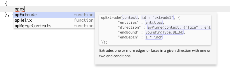
This will insert the following code:
opExtrude(context, id + "extrude1", { "entities" : entities, "direction" : evOwnerSketchPlane(context, {"entity" : entities}).normal, "endBound" : BoundingType.BLIND, "endDepth" : 1 * inch });NOTE
Functions in the standard library with the "`op`" prefix are **operations**. These functions all perform some change to the context which modifies its geometry.Often, there will also be a feature function which calls the operation (in the case of extruding, the
extrudefeature calls theopExtrudefunction). The feature is wrapper which provides a nice Part Studio interface on top of that operation, sometimes with additional operations (for instance, theextrudeincludes additional parameters to optionally add a boolean and a draft). In FeatureScript, it's often a better idea to call the operation directly.After insertion, you should see the parameter "
context" highlighted. This is theContext, a data structure which contains all geometry in the Part Studio. Almost always, your features will involve a singleContextnamed "context", passed in from the Part Studio. Here, we pass it on to theextrudefunction so thatextrudecan create geometry in the Part Studio.The default autocompletion of "
context" makes sense, so leave it.opExtrude(context, id + "extrude1", { "entities" : entities, "direction" : evOwnerSketchPlane(context, {"entity" : entities}).normal, "endBound" : BoundingType.BLIND, "endDepth" : 1 * inch });With the tab key or the mouse, select the next parameter:
id + "extrude1". This is theId, a unique identifier for the extrude operation being performed.The default
Idis already unique and descriptive, so leave it.opExtrude(context, id + "extrude1", { "entities" : entities, "direction" : evOwnerSketchPlane(context, {"entity" : entities}).normal, "endBound" : BoundingType.BLIND, "endDepth" : 1 * inch });NOTE
An **Id** is a hierarchical identifier for a specific operation or feature. When the Part Studio creates a slot feature, a unique `Id`, named "`id`", is passed in. Each slot feature created will have a different unique id.The expression
id + "extrude1"creates a sub-id of this feature'sid. We use the sub-id to label this specific invocation of theextrudefeature. Thus, each instance of a slot will contain an instance of an extrude, all labeled uniquely (idForSlot1 + "extrude1",idForSlot2 + "extrude1", etc.).As we will see soon, any
Idcan be used in a later operation to specify the geometry created by the feature or operation with that id. This will include any geometry created by sub-ids.Select the text next to the
"entities"field. This field defines what geometry should be extruded. We want to extrude the sketch edge passed in. This edge is stored on on thedefinitionasslotPath, as we defined in the precondition.Change the entities field to
definition.slotPath:opExtrude(context, id + "extrude1", { "entities" : definition.slotPath, "direction" : evOwnerSketchPlane(context, {"entity" : entities}).normal, "endBound" : BoundingType.BLIND, "endDepth" : 1 * inch });Select the text next to the
"direction"field. This field defined what direction to extrude in. We want this feature to extrude the surface perpendicular to the sketch normal.The default autocompletion makes a call to the
evOwnerSketchPlaneget the correct direction vector. We want to do the same, but instead evaluate the owner sketch of theslotPath.opExtrude(context, id + "extrude1", { "entities" : definition.slotPath, "direction" : evOwnerSketchPlane(context, {"entity" : definition.slotPath}).normal, "endBound" : BoundingType.BLIND, "endDepth" : 1 * inch });NOTE
Functions from the standard library with the "`ev`" prefix are **evaluations**. These functions all obtain data and/or measurements from the entities inside a context.The result of an evaluation function is a value which can be used in subsequent calculations. For instance,
evOwnerSketchPlanereturns a value with typePlane. APlanehas the information define its position and orientation in 3D space, including a 3D unitVectordefining the plane's normal direction. Above, we use thisnormalfield above as the extrude direction.Press tab to select the text next to the
"endBound"field. This field specifies aBoundingType: one ofBLIND,THROUGH_ALL, etc.Change the endBound to "
BoundingType.THROUGH_ALL":opExtrude(context, id + "extrude1", { "entities" : definition.slotPath, "direction" : evOwnerSketchPlane(context, {"entity" : definition.slotPath}).normal, "endBound" : BoundingType.THROUGH_ALL, "endDepth" : 1 * inch });Press tab to select the text next to the
"depth"field. Since we've chosen aTHROUGH_ALLextrude, this field isn't necessary.Delete the entire depth parameter:
opExtrude(context, id + "extrude1", { "entities" : definition.slotPath, "direction" : evOwnerSketchPlane(context, {"entity" : definition.slotPath}).normal, "endBound" : BoundingType.THROUGH_ALL, "endDepth" : 1 * inch });In its place, we will specify that the start bound of the extrude should also be
THROUGH_ALL.This addition gives us some extra robustness in making sure the slot cuts properly. In the one instance we've made in a Part Studio, we defined the slot sketch on the bottom surface of the part, so the sketch normal points directly into the part. However, we want this feature to still work if a user puts a sketch on the top surface, or in the center, or even off of the part.
Add the field
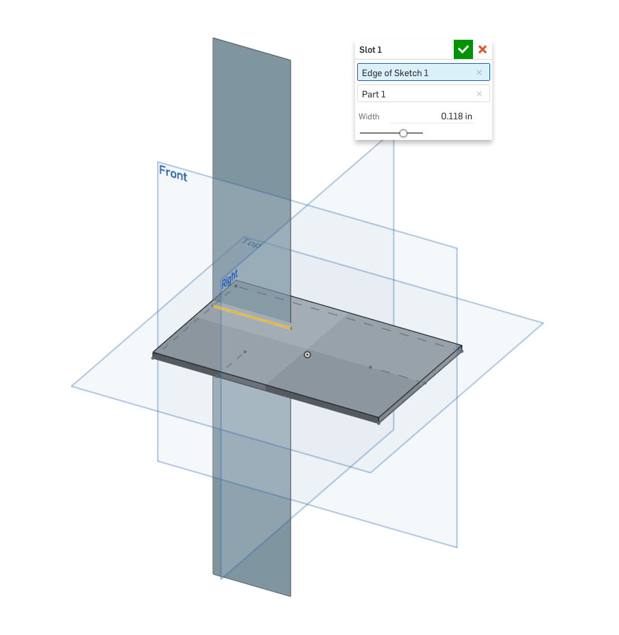
"startBound" : BoundingType.THROUGH_ALLas the last field in the extrude call:opExtrude(context, id + "extrude1", { "entities" : definition.slotPath, "direction" : evOwnerSketchPlane(context, {"entity" : definition.slotPath}).normal, "endBound" : BoundingType.THROUGH_ALL, "startBound" : BoundingType.THROUGH_ALL });Press the commit button. At this point, your FeatureScript notices panel should be free of errors.
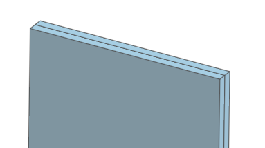
If you switch back to the Part Studio, you should see a surface extruded from the edge in your slot feature in two directions:
The next operation will thicken the surface to the slot width.
After the
extrudecall, type and select the autocompletion foropThicken. This will insert the following code:opThicken(context, id + "thicken1", { "entities" : entities, "thickness1" : 0.1 * inch, "thickness2" : 0.1 * inch });For this operation, the
contextshould be left as "context", as usual. TheIddefault of "id + "thicken1"" is unique and descriptive, so leave that too.The
"entities"should specify the surface to thicken. Specify a query for the surface we just created usingqCreatedBy, passing in the id of the first extrude:opThicken(context, id + "thicken1", { "entities" : qCreatedBy(id + "extrude1", EntityType.BODY), "thickness1" : 0.1 * inch, "thickness2" : 0.1 * inch });NOTE
A **Query**, like `qCreatedBy`, is a way to refer to topological entities (vertices, edges, faces, and bodies) in FeatureScript.You can think of a query as an order form for entities, with one or more criteria that the specified entities must satisfy. The query itself does not contain the entities. Rather a query specifies a set of entities in a context (remember: the context contains all the geometry). When you pass a query into an operation function, that function uses the query and the context to perform the operation on the right entities.
Other examples of queries are the two query parameters you've defined:
slotPathandpartToCut. These queries are generated automatically when a user selects entities, and stored in the fieldsdefinition.slotPathanddefinition.partToCut. The generated queries refer to the selected entities in a robust way so that features can be resistant to upstream changes. For instance, if a user selects an edge on the cap face of an extrude, then later flips the direction of that extrude, they'll find the downstream feature now has the same edge selected on the opposite side of the extrude, as expected.A query may evaluate to zero, one, or many entities. To see all the queries FeatureScript has available, refer to the Query module.
thickness1andthickness2specify how much to thicken on each side of the surface. Let's make the slot symmetric, and thicken each side by half the slot width:opThicken(context, id + "thicken1", { "entities" : qCreatedBy(id + "extrude1", EntityType.BODY), "thickness1" : definition.width / 2, "thickness2" : definition.width / 2 });Press the commit button. In your Part Studio, you should see the thickened surface: a new solid body in your
Context.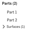
The thicken operation did not delete the original extruded surface, so let's clean that up now. Type and select the autocompletion for
opDeleteBodies. This will insert:opDeleteBodies(context, id + "deleteBodies1", { "entities" : entities });Leave the default
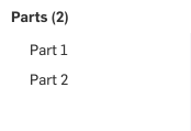
ContextandId, and set the"entities"to "qCreatedBy(id + "extrude1", EntityType.BODY)", the same query for the surface body created by the extrusion:opDeleteBodies(context, id + "deleteBodies1", { "entities" : qCreatedBy(id + "extrude1", EntityType.BODY) });In your Part Studio, you should see the extruded surface disappear, but the new thickened body should still be present:
The final operation will subtract the thickened surface from the specified "Part to cut". Type and select the autocompletion for
opBoolean:opBoolean(context, id + "boolean1", { "tools" : tools, "operationType" : BooleanOperationType.UNION });Leave the default
ContextandId, and set the following parameters:"tools", the parts to subtract, should be the result of the Thicken operation: "qCreatedBy(id + "thicken1", EntityType.BODY)""targets", the parts to be cut, should be set to the part set on the definition: "definition.partToCut""operationType", the boolean operation to perform, should be "BooleanOperationType.SUBTRACTION"
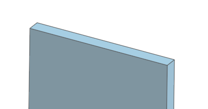
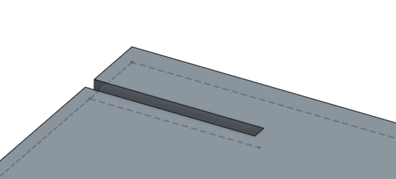
opBoolean(context, id + "boolean1", { "tools" : qCreatedBy(id + "thicken1", EntityType.BODY), "targets" : definition.partToCut, "operationType" : BooleanOperationType.SUBTRACTION });In your Part Studio, you should now see the slot correctly cut out of your part, and the thickened body deleted:
Congratulations! You've just completed your first FeatureScript feature.
Feel free to play around with the feature. The slot feature function will be called again (i.e. regenerated) every time you change a slot feature's parameters, or change a feature upstream of a slot feature in the feature tree. After you update a Feature Studio and commit your changes, dependent Part Studios will also be regenerated.
Try creating test cases for this feature. Where does the feature succeed? Where does it not do what you expect? How could the design be improved?
Review
In this tutorial, we've discussed how to:
- Create a new feature type
- Define definition parameters
- Filter for different kinds of geometry by EntityType and BodyType
- Modify geometry with operations
- Keep track of operations and features with hierarchical ids
- Get geometrical information from entities with evaluations
- Specify geometry with queries
- Update other tabs via commit
- Add code quickly with the autocomplete menu
- Navigate inserted code with autocomplete regions
In the next tutorials, we will cover more FeatureScript topics while refactoring the way our slot feature is created and improving its behavior.
Final feature code
Included here is the final code written in this tutorial. Note that your FeatureScript version and Onshape Standard Library version may be different.
FeatureScript 1890;
import(path : "onshape/std/common.fs", version : "1890.0");
annotation { "Feature Type Name" : "Slot" }
export const slot = defineFeature(function(context is Context, id is Id, definition is map)
precondition
{
annotation { "Name" : "Slot path", "Filter" : EntityType.EDGE, "MaxNumberOfPicks" : 1 }
definition.slotPath is Query;
annotation { "Name" : "Part to cut", "Filter" : EntityType.BODY && BodyType.SOLID, "MaxNumberOfPicks" : 1 }
definition.partToCut is Query;
annotation { "Name" : "Width" }
isLength(definition.width, LENGTH_BOUNDS);
}
{
opExtrude(context, id + "extrude1", {
        "entities" : definition.slotPath,
        "direction" : evOwnerSketchPlane(context, {"entity" : definition.slotPath}).normal,
        "endBound" : BoundingType.THROUGH_ALL,
        "startBound" : BoundingType.THROUGH_ALL
});
opThicken(context, id + "thicken1", {
        "entities" : qCreatedBy(id + "extrude1", EntityType.BODY),
        "thickness1" : definition.width / 2,
        "thickness2" : definition.width / 2
});
opDeleteBodies(context, id + "delete1", {
"entities" : qCreatedBy(id + "extrude1", EntityType.BODY)
});
opBoolean(context, id + "boolean1", {
        "tools" : qCreatedBy(id + "thicken1", EntityType.BODY),
        "targets" : definition.partToCut,
        "operationType" : BooleanOperationType.SUBTRACTION
});
});