PCB Studios
![]()
僅為 提供。
Onshape PCB Studios 可讓您使用 ECAD 檔案做為參考來建立模型。PCB Studios 幫助您使用 Onshape 來建立印刷電路板的形狀,以 IDF 格式匯出在 Onshape 中建立的這些模型,再將其傳送給電子工程師以在 ECAD 系統中用來建立 PCB 設計。
您也可以用 IDF、IDX 與 Eagle 格式匯入 ECAD 檔案,然後使用檔案來建立 Onshape Part Studio 與組合件,以在建立電路板外盒時用為參考。
若要將 PCB Studio 加入至您的 Onshape 文件中:
-
按一下左下方的「插入新分頁」(
 ) 圖示。
) 圖示。 -
選擇 [建立 PCB Studio]。
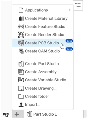
在您的文件中有 PCB Studio 之後,會看到像是這樣的分頁:
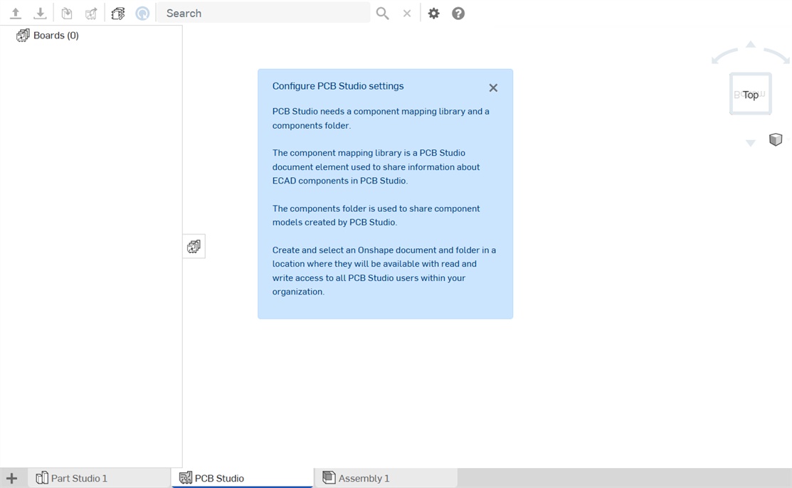
圖示定義
| 圖示 | 名稱 | 定義 |
| 工具列圖示 | ||
|
|
Import ECAD files | 將 ECAD 檔案匯入至這個 PCB Studio 中。 |
|
|
Export to IDF | 將這個 PCB Studio 匯出為 IDF 格式。 |
|
|
Sync from Onshape | 將 Part Studio 或組合件與這個 PCB Studio 同步來建立一個電路板,或是更新電路板的板框、零組件位置、阻出、阻進與其他 ECAD 功能 (匯入)。 |
|
|
Sync to Onshape | 建立來自 ECAD 資料的 Part Studios 或組合件以將這個 PCB Studio 與 Onshapeor 同步 (匯出)。 |
|
|
Update library to latest version | 當已在另一個 PCB Studio 中修改文件時,將在這個 PCB Studio 中的資源庫文件更新至最新的版本。 |

|
Search | 在目前視圖中搜尋 3D 預覽中的零組件或阻出/組進區域。在對應視圖中搜尋零組件的對應。 |

|
Clear search | 清除搜尋。 |
|
|
設定 | 設定使用者的喜好設定,包括預設的零組件對應資源庫以及新建立 Onshape 文件的零組件資料夾。 |
|
|
Help | 在另一分頁中開啟 PCB Studio 說明文件。 |
| 電路板、資源庫、與零組件圖示 | ||
|
|
Boards and Libraries | 顯示目前 PCB Studio 中所有的電路板與資源庫。 |
|
|
All component mappings | 顯示儲存在 PCB Studio 中的所有零組件。 |
|
|
Linked board | 表示電路板是連結的 |
|
|
Mappings | 電路板對應 |
|
|
No footprint | 不會為這個零組件對應在 Onshape 中建立任何項目。零組件並未由任何 Onshape 模型來代表,可能是因為在 ECAD 檔案中沒有定義形狀的資料,或是使用者選擇不將這個零組件包含在 Onshape 中。 |
|
|
Footprint | 零組件在 Onshape 中是由一個模型所代表,這個模型是從 ECAD 檔案中的簡單形狀資料自動產生的。不過,尚未建立 Onshape 模型。 |
|
|
Linked footprint | 零組件在 Onshape 中是由一個模型所代表,這個模型是從 ECAD 檔案中的簡單形狀資料自動產生的。尚未建立 Onshape 模型,且是連結的。 |
|
|
Component | 零組件在 Onshape 中是由使用者選擇的自訂 Onshape Part Studio 所代表,但目前無法使用文件。可能已將文件移至垃圾桶中,或權限有所更改而使得這個使用者無法存取文件。 |
|
|
Linked component | 零組件在 Onshape 中是由使用者選擇的自訂 Onshape 零件所代表。 |
|
|
Component error | 在建立這個零組件的 Onshape 模型過程中發生錯誤。 |
|
|
Rigid board | 表示硬性電路板的區域。 |
|
|
Flexible board | 表示軟性電路板的區域。 |
|
|
Board outline | 表示電路板的板框。 |
|
|
PCB Outline | 表示電路板上的邊框。請注意這與 PCB 板框並不相同。這是使用者在電路板的 ECAD 系統中定義的區域 (類似於阻進或阻出區域)。例如,可以用來表示 MCAD 使用者要放置標籤的位置。 |
|
|
Keep-in area | 阻出區域 (應放置項目的區域)。 |
|
|
Keep-out area | 阻進區域 (不可放置項目的區域)。 |
|
|
Hole | PCB 板上的孔。 |
|
|
Electrical hole | PCB 板上的電子孔。 |
|
|
Mechanical hole | PCB 板上的機械孔。 |
|
|
Layers | PCB 板上的各層。 |
|
|
Stackup | 表示層的堆疊 (構成這個電路板或電路板區域的 z 平面上的層堆疊)。 |
|
|
Dielectric | 表示介電 (絕緣) 電路板層。 |
|
|
Copper | 表示銅 (導電) 電路板層。 |
您可以檢視:
-
Boards - 已匯入至這個特定 Onshape 文件 PCB Studio 中所有電路板的清單。可以從已匯入的 ECAD 檔案來產生電路板,或從包含電路板的已匯入 Onshape Part Studio 或組合件來產生電路板。
當從 Onshape Part Studio 或組合件中匯入時,模型必須與三個預設平面之一平行,且零件名稱中必須包含關鍵字 “Board” 或 “PCB” 才能確保適當的轉譯。請參考下方的命名零件。
-
Components - 已匯入至 PCB Studio 中所有 ECAD 資料內的完整零組件清單,並會有零組件的形狀和與其相關 Onshape 模型 (如果模型存在的話) 的連結。Onshape PCB Studio 會自動為每個 ECAD 零組件使用定義在 ECAD 資料中的簡單形狀來在新文件中建立 Onshape Part Studio。不過您也可以選擇改使用自訂的零件來代表零組件。
根據預設,系統會將所有的零組件資訊儲存在另一個 Onshape 文件中 (用做為中央資源庫)。這樣可確保零組件形狀與相關的 Onshape 模型可供多個文件與多個使用者重複使用。這個文件的位置是在 PCB Studio 設定中定義的。
當在 PCB Studio 中有一或多個電路板時,會顯示參考這些電路板的零組件。
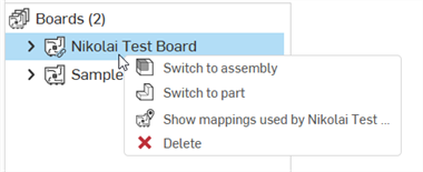
電路板環境選單
在電路板上按右鍵來存取下列的選項:
-
Switch to assembly - 切換至組合件分頁。
-
Switch to part - 切換至 Part Studio 分頁。
-
Show mappings used by [電路板] - 顯示所選電路板的所有零組件對應。
-
Delete - 刪除所選的電路板。
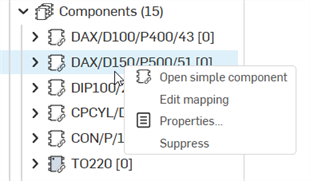
零組件環境選單
在零組件上按右鍵來存取下列的選項:
-
Open detailed component - 在零組件的來源文件中開啟零組件的 Part Studio。會在新的瀏覽器分頁中開啟。
-
Edit mapping - 在右側面板中開啟零組件的零組件對應屬性。請參考在這個主題中稍後的 ECAD 腳位與零組件的對應。
-
Properties - 在右側面板中開啟「Component properties」。請參考 Component properties。
-
Suppress/Unsuppress - 抑制會從 ECAD 資料中移除一個零組件。當資料中包含您不要在組合件中看到但要在 ECAD 資料中看到的零組件時,這是相當有用的。取消抑制會將零組件加回到 ECAD 資料中。
選擇最上層的 Keep-in area 對 Suppress all 提供額外的選項,或 Unsuppress all Keep-in areas 下方的項目:

首次使用的設定
使用者第一次使用 PCB Studio 時,使用者 (通常是公司或企業管理員) 必須執行下列的操作:
-
建立 PCB Studio 的零組件資料夾,以儲存建立於 PCB Studio 中所有的零組件模型。這個資料夾必須可供公司/企業內所有的 PCB Studio 使用者存取。
-
在所有公司/企業使用者都有存取權限處建立一個文件來做為共享的 PCB Studio 資源庫。如果是在零組件資料夾中建立了 PCB Studio 資源庫文件,當從這個資料中刪除不要的零組件模型時,請小心不要意外刪除該文件。
-
將一個 PCB Studio 元素加入至上方步驟 2 所建立的文件中,然後建立該文件的一個版本。在完成之後,這個文件即可做為 PCB Studio 資源庫來使用。
-
前往另一個 PCB Studio 文件中,然後設定將 PCB Studio 設定參考這個資源庫文件與資源庫資料夾 (請參考下方的 PCB Studio Settings 對話方塊)。
不應使用這個資源庫資料夾與文件來開啟或建構 ECAD 檔案。在建立這個資料夾與文件之後,使用者於正常情況之下應不需要打開它。這個資源庫的存在僅做為組織中 PCB Studio 使用者之間共享的資料庫,用來儲存零組件對應資訊 (例如,哪個 Onshape 模型是用於哪個 ECAD 零組件)。
「PCB Studio Settings」對話方塊
使用零組件資訊設定來設定一個預設文件,以在其中儲存所有的 ECAD 零組件對應,這樣無論您在 Onshape 中操作的文件為何,都可以使用在 PCB Studio 中提供的零組件對應。同時使用這些設定來指定一個資料夾,以於其中建立新的模型文件 (從應用程式中匯出 ECAD 模型到 Onshape 中建立的文件)。
按一下「Settings」圖示 (![]() ) 來存取「PCB Studio Settings」對話方塊:
) 來存取「PCB Studio Settings」對話方塊:
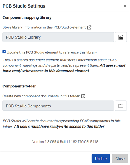
零組件資訊設定可讓您將所有的 ECAD 零組件對應收集到單一的文件中,所以您可以在任何文件中使用 PCB Studio (在連接至單一文件來取得零組件對應時)。在這個欄位中選擇文件的 URL (供您方便使用,可以按一下方塊箭號來在新的瀏覽器分頁中開啟該文件)。
當指定要儲存模型文件 (從應用程式中匯出 ECAD 模型到 Onshape 中建立的文件) 的資料夾時,請確定有資料夾存在且您可以在 Onshape 中存取它。
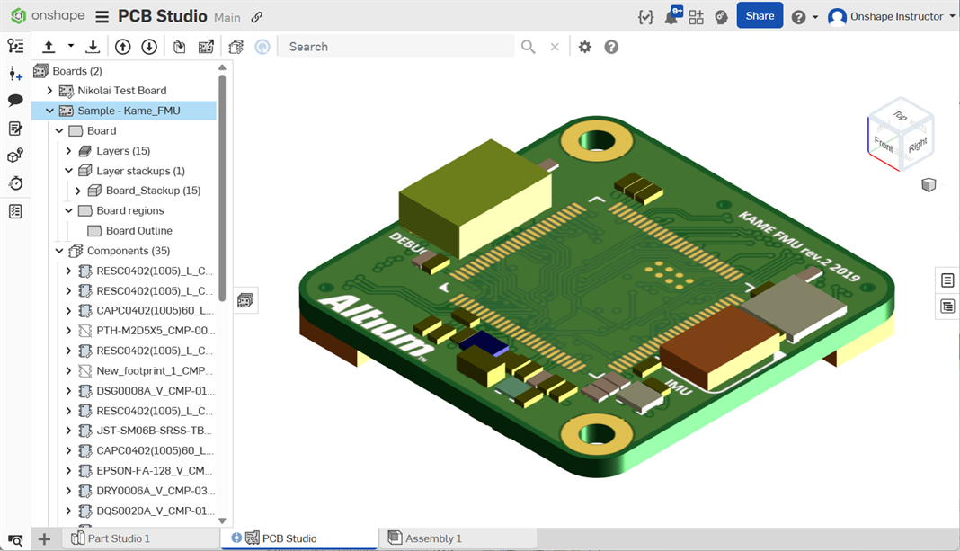
將您的 ECAD 檔案匯入至 PCB Studio 中,檔案會以電子資料存在。下一步是將資料從 PCB Studio 轉譯到 Onshape 內,然後將其轉換為 Onshape 組合件。在您對設計做出需要的修改之後,回到 PCB Studio 分頁中並將 Onshape 資料移回至 PCB Studio,再將資料轉譯回電子資料。
將電子 CAD 資料帶入 PCB Studio 中有四大步驟,在 Onshape 中使用資料然後將其帶回:
-
將 ECAD 檔案匯入至 PCB Studio (Onshape 中的一個分頁)。
-
將 ECAD 資料轉譯成 Onshape Part Studio 與 Assembly 中的 3D CAD 資料,然後進行所需的變更。
-
將在 Onshape 中建立的新資料轉譯回 PCB Studio 中。
-
將 ECAD 資料匯出 PCB Studio 並傳送給電子工程師或廠商。
下方將詳細說明每個步驟。
匯入 ECAD 檔案
在您的 Onshape 文件中有 PCB Studio 之後,請匯入 ECAD 檔案:
-
啟動您 Onshape 文件中的 PCB Studio 分頁。
-
按一下
 來將包含部分或完全定義電路板的 ECAD 檔案匯入至 PCB Studio 中。
支援的檔案類型包括:
-
IDF 2.0 及 3.0 (.emn / .emp, .bdf / .idf, .brd / .pro, .brd / .lib)
-
IDF 3.0, 3.5 與 4.0 (.idx)
-
Autodesk Eagle v6 與更高的版本 (.brd)
-
這個時候資料已載入至應用程式,您可以選擇將每個 ECAD 零組件的腳位對應至:
-
無模型
-
來自上傳檔案中的原始 ECAD 腳位
-
Onshape 文件中的自訂零件
關於建立對應的詳細資訊,請參考這個主題稍後會說明的 ECAD 腳位與零組件的對應。
匯入 PTC Creo hint.map 檔案
hint.map 檔案是一個 PTC Creo 文字檔案,其中儲存由 Creo 的 ECAD/MCAD 轉譯程式所使用的 ECAD 零組件零件名稱與編號的清單。可以將這些檔案匯入為一個 ECAD 檔案以將相同的資訊移入至 PCB Studio 零組件對應資源庫中。
僅會匯入零組件名稱與編號。檔案所參考的任何 Creo 零組件模型都必須匯入至 Onshape 中,且手動加入到 PCB Studio 內。
請根據下方的步驟操作來匯入檔案:
-
按一下 Import ECAD files(
 ) 按鈕。
) 按鈕。 -
按一下 Choose Files 按鈕:

-
找出在您裝置中的檔案,然後按一下開啟。
-
按一下 Import 按鈕。
-
系統會開啟一個匯入的通知,說明加入與更新的零組件數量。按一下通知右上角的關閉按鈕 (
 )。
)。 -
按一下工具列上的 All component mappings 按鈕 (
 )。新的零組件對應會顯示在資源庫中:
-
在匯入 hint.map 檔案時,會對應下列的欄位:
-
ECAD_NAME 對應至 Part name
-
ECAD_ALT_NAME 對應至 Part number
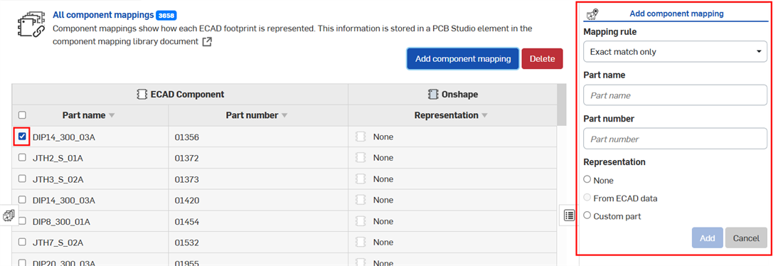
這些新資源庫零組件在 Onshape 並無任何代表 (Representation 欄是被設定為 None)。這是因為在 hint.map 檔案中並沒有任何 3D 模型的資訊。若要設定零組件的 Representation:
-
核取零組件的列。
-
按一下「Add component mapping」按鈕來在右側開啟「Add component mapping」面板:
-
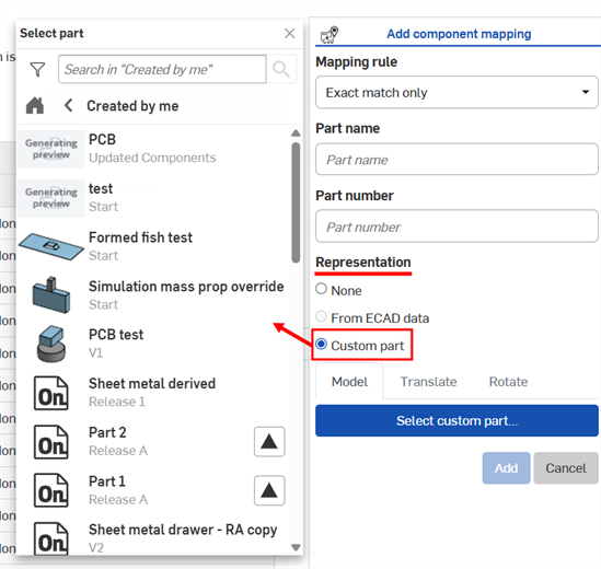
在「Representation」下方選擇「Custom part」。
-
在開啟的「Select part」對話方塊中,找出並選擇零件:
-
轉譯 ECAD 資料
在將 ECAD 檔案載入至 PCB Studio 之後,您需要將資料轉譯為 3D CAD 資料以在 Onshape Part Studio 與 Assembly 中使用:
-
在 PCB Studio 分頁啟用的情況下,按一下「Sync to Onshape」圖示 (
 ) 來將在 PCB Studio 分頁中的 ECAD 資料轉譯至 Onshape 中。資料會以 Onshape 文件的方式呈現,Part Studio 代表電路板以及任何阻進與阻出區域,組合件則包含電路板 Part Studio 與電路板上所有的零組件。
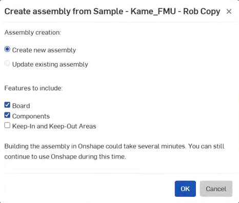
系統會為每個 ECAD 零組件建立一個新的 Onshape 文件,並將其儲存在由使用者設定指定的預設資料夾中。所有產生的零件會出現在一特定資料夾中,其中包含為每個連結零件與版本零件產生的個別文件。例如,在文件頁面中的資料夾,如下所示:
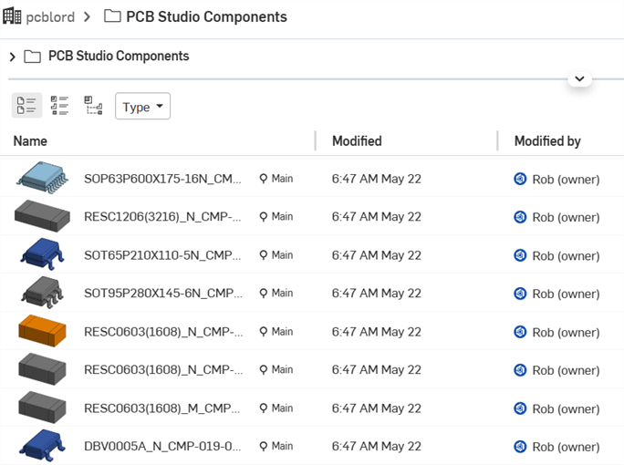
您資料夾的名稱可能與上方顯示的不同。
如果需要,您可以隨意重組資料夾中的內容,或是將內容移出資料夾。
-
選擇您要包括在 Onshape 模型中的特徵:
-
Board - 在 Onshape Assembly 中包括電路板
-
Components - 包括可在 Onshape Assembly 內檔案找出的所有零組件
-
Keep-in 與 Keep-out areas - 包括在 Onshape 組合件中的阻出與阻進區域。
-
-
按一下 [匯出] 按鈕。
系統會建立兩個新分頁:一個 Part Studio 與一個 Assembly。同時會使用 Board 或在 ECAD 檔案中定義的 (如果有的話) PCB 名稱來命名。
此時您可以啟動以剛轉譯電路板命名的 Part Studio 或 Assembly 分頁,然後根據需要建構模型。您可以將經轉譯資料用做為模型建構的參考,甚至使用 Onshape 工具來編輯資料 (如果需要的話)。例如:
-
啟用新建立的 Part Studio 分頁。
-
使用 Onshape 模型建構工具,視需要設計電路板外盒或編輯電路板 (如範例中所示),使用 ECAD 資料做為 Part Studio 中的參考 (您不僅可以使用 ECAD 資料做為模型的參考點,也可視需要編輯 ECAD 本身資料)。
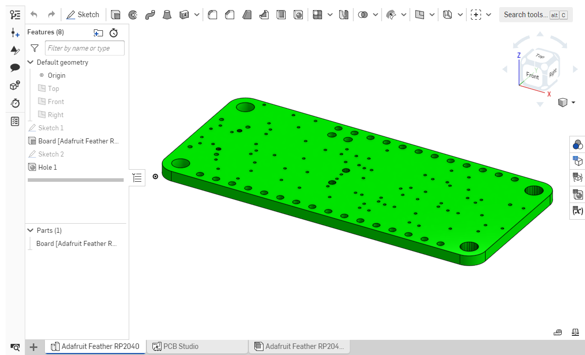
注意到上圖中新建立 Part Studio (Adafruit Feather.) 與組合件 (Adafruit Feather)
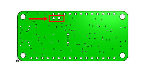
上圖的範例顯示經編輯的電路板區域,其中有在 Onshape 中建構的額外鑽孔。
請注意,如果您為電路板建構了其他的零組件,每個單一零組件應在自己的 Part Studio 中。
在 Part Studio 中完成模型建構之後,您可以更新組合件以反映在 Part Studio 中做出的變更。
在 Part Studio 中編輯電路板之後,您可以在組合件中置換該電路板,請開啟組合件分頁,然後在電路板上按右鍵並選取 [取代實例]。選擇用來取代組合件中實例的零件,系統即會以電路板的新實例更新組合件。
將 CAD 資料轉譯至 ECAD
當在 Onshape 中完成所有的模型建構,且以新的資訊更新組合件後,您需要將存在 Onshape 中的 CAD 資料轉譯回 PCB Studio 應用程式中,才能夠將資訊以 IDF 檔案匯出應用程式。
在您從 PCB Studio 參考 Onshape 資料之前,了解會發生的狀況與可預期事項是相當重要的。
這個動作 (從 Onshape 中轉譯資料到 PCB Studio) 會分析在組合件中零件的形狀與位置,然後將這些資訊轉換成 ECAD 資料。若要達成此目的,有幾件事是相當重要的:正確地命名零件、零件各自存在於自己的 Part Studio 中,以及組合件的組裝可讓 PCB Studio 正確地決定每個零件所代表的項目。
代表電路板或 PCB 的單一 Part Studio 中應包含一個名為 Board 或 PCB 的零件,代表阻進或阻出區域的選用零件應以下方的規則命名。任何 Part Studio 中包含不是 Board 或 PCB 名稱的零件將被視為零組件。
-
按一下「Sync a Part Studio or Assembly with PCB Studio」圖示
 以將來自 Onshape Part Studio 或組合件中的資料轉譯回 PCB Studio 分頁。
 -
「Sync a part studio or assembly with PCB studio」對話方塊開啟:
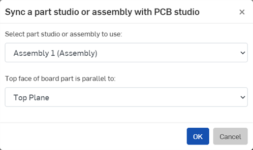
-
選擇適當的 Onshape 分頁 (Part Studio 或組合件)。如果 Part Studio 或組合件有清單組態,會在「Select part studio or assembly to use」下拉清單中以個別的方括弧項目列出第一個最常的清單組態 (例如,下方所示的 [Configuration = Configuration A]):
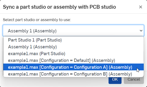
-
選擇與電路板的正面平行的平面:
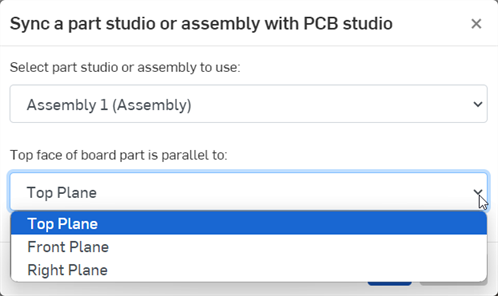
-
-
當這個操作成功時,會在電路板清單中建立一個電路板,然後資料會與組合件同步:
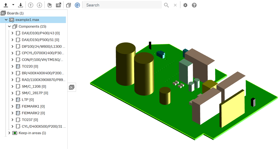
將發生的狀況:
對於組合件中的每個零件,PCB Studio 會檢查該零件是否已有零組件對應存在。如果有對應存在,則轉譯的過程會假定零件代表的是一個現存的 ECAD 零組件。如果零組件是既存的,則只會轉譯零組件的位置,因為已經知道零組件形狀。
如果沒有對應存在,則過程會假定零件代表的是電路板,阻出或阻進區域,或是沒有對應的零組件。
在匯入的過程中,會在電路板名稱旁出現一個進度環。若要取消匯入,請按一下紅色的 X。
命名零件
Part Studio 中每個零件的名稱會用來決定 Part Studio 包含那些 ECAD 特徵類型或類型。ECAD 假定下列的零件名稱>ECAD 項目類型配對 (注意到名稱不區分大小寫):
| 零件名稱包含 | ECAD 假定的項目類型 |
| 電路板 | Board outline |
| PCB | Board outline |
| 區域 | 剛性電路板區域或範圍 (僅適用於 IDX 檔案類型) |
| Rigid | 剛性電路板區域或範圍 (僅適用於 IDX 檔案類型) |
| Flex | 撓性電路板區域或範圍 (僅適用於 IDX 檔案) |
| Keep-in/Keepin | 阻出區域 (應放置項目的區域) |
| Keep-out/Keepout | 阻進區域 (不可放置項目的區域) |
|
Outline Outline [零件名稱] |
IDF 3.0 .OTHER_OUTLINE - 用於板框之外作用的帶切口板框,像是防焊層、散熱或電路板核心。 如果在零件名稱中使用了 "Outline",則 "Outline" 會列在 Component Properties 中。如果在方括弧中放置了其他的名稱 (例如,"Outline [Soldermask]",則 "Soldermask" 會列在 Component Properties 中)。 |
將下列的文字與阻出、阻進或板框的名稱合併可向 ECAD 表達意圖。例如,名為 Place keepout 的特徵可解讀為零組件的阻進區域,也就是 ECAD 不應於其中放置任何零組件的區域:
-
Components 或 Place - 零組件阻出、阻進或板框
-
Via - 透過阻出、阻進或板框
-
Route / Routing / Copper/ Trace - 佈線阻出、阻進或板框
僅使用 Routing、Route、Copper 或 Trace 名稱而沒有其他文字來指明特徵是阻出、阻進或板框會被解讀成銅走線或佈線的區域。尚不支援這些特徵類型的匯出,所有目前僅保留這些名稱以供之後使用。
有其他名稱 (例如 0402C) 的零件會被解讀為零組件。如果零組件尚未被對應所參考,則零件名稱會同時被用為 ECAD 零件名稱與零件編號。建議您避免直接在 Onshape 組合件中新增 ECAD 零組件。
匯出資料並下載檔案
現在如果需要的話,您可以將資料從 Onshape 的 PCB Studio 分頁匯出為 IDF 檔案,並傳回給電子工程師。
按一下  :
:
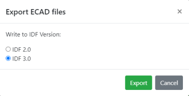
選擇所需的 IDF 版本然後按一下 [匯出]。系統會將檔案下載至本機中。
在匯出為 IDF 格式之後,會將某些特殊字元轉換為連字號 (-) 來與其他第三方 ECAD 系統相容。例如,會把匯出.zip 檔案內所有檔案的 board 1.max [Configuration_ Default] 轉換為 board 1-max -Configuration- Default-。
在視窗右側的「Component properties」分頁中,您可以檢視於圖形區域中所選電路板或零組件的屬性:
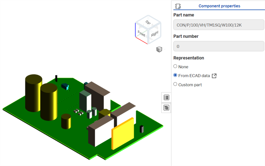
上圖中以金色強調顯示選取的零組件,並顯示「Component properties」窗格
這個時候您可以選擇加入或變更與零組件相關的模型:
-
選擇您所要對應的模型類型:
-
無 (系統不會為這個 ECAD 零件加入任何項目至 Onshape 中)
-
來自 ECAD 資料 (保留由 ECAD 系統所提供的形狀)
-
自訂零件 (來自 Onshape Part Studio 的一個零件)
-
-
如果您選擇「Custom part」,會出現更多的欄位:
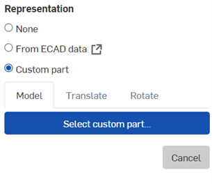
-
如果已用現有的 Onshape 模型來代表零組件,則會顯示一個縮圖圖片和零組件的名稱。如果需要,請按一下縮圖圖片來瀏覽至另一個 Onshape 零件。
-
在沒有現存 Onshape 零件的所在處,按一下 [Select custom part]。
-
系統會開啟一個對話方塊,您可於其中選擇一個 Onshape 文件,這個文件包含您要取代電路板中所選零件的零件。
-
從清單中選擇零件。
新的零件會取代所選的零件。
按一下 ![]() 來在 Onshape 的獨立分頁中開啟包含該零件的 Part Studio。
來在 Onshape 的獨立分頁中開啟包含該零件的 Part Studio。
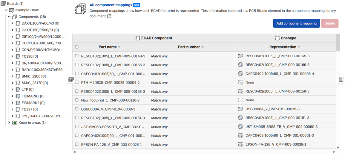
零組件視圖會列出目前已匯入至 PCB Studio 的每個 ECAD 檔案內的各個 ECAD 零件名稱與零件編號 (或零組件腳位)。
左邊的兩個欄位顯示每個 ECAD 零組件腳位的零件名稱與編號。右邊的欄位顯示 PCB Studio 如何在 Onshape 中呈現該 ECAD 零組件。這種關係稱為「零組件對應」。
根據預設,PCB Studio 使用在 ECAD 資料中定義的簡單形狀來為每個 ECAD 腳位自動產生一個簡單的 Onshape 模型。不過,您也可以選擇性地使用一個自訂零件,以在 Onshape 中更詳盡地呈現零組件,或是選擇完全不在 Onshape 中顯示零組件。
顯示在每個零組件旁的圖示指出該零組件在 Onshape 中的呈現方式。關於每個圖示的詳細資訊,請參考圖示定義。
目前 Part Studios 或零件是對應至零組件的。無法將已組態零件對應為零組件。
若要檢視 (與編輯) 零組件對應:
-
在工具列中選擇 All component mappings 圖示 (
 ) 來在右側的窗格中顯示所有 ECAD 腳位的清單與相關的 Onshape 模型。從面板左側的 Boards and Libraries 中開啟一個電路板並選擇該電路板的一個子零組件節點以僅顯示與該電路板相關的零組件對應。
-
您可以在清單中手動找出要尋找的零件,或您可以搜尋零件:
-
使用搜尋列:

-
按下 Enter 鍵或按一下「搜尋」按鈕來檢視結果。搜尋列會指出找到實例的數量,並強調顯示第一個找到的項目。點按向下或向上箭頭來循環瀏覽結果。注意到使用箭頭循環瀏覽結果時,對應的清單並未變更:
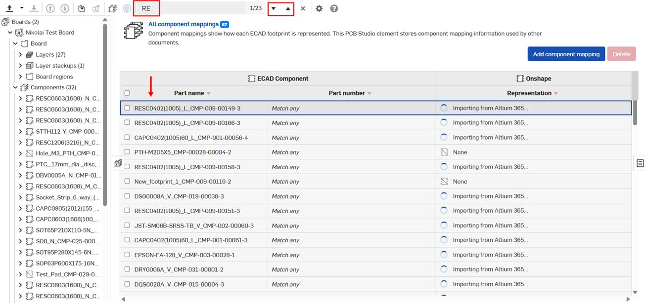
-
-
當您找出需要的零件時,點按零件以開啟零組件:

如果需要,您可以將零組件的呈現方式改為自訂的 Onshape 零件,詳細資訊請參考 Component properties。
-
零組件腳位會於主圖形區域中開啟。Component mapping 窗格則會於右側開啟,您可於其中編輯 Mapping rule、Part name 與 Part number:
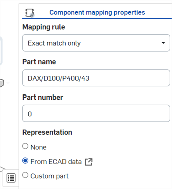
-
選擇下方的一個 Mapping rule:
-
Exact match only - 僅將零件與確切的 Part name 和 Part number 配對。
-
Match any part name - 與任何零件名稱配對。
-
Match any part number - 與任何零件編號配對。
-
-
選擇一個「Part name」、「Part number」與「Representation」(於上方 Component properties > 步驟 2 中所述)。
PCB Studio 會為 PCB Studio 中的電路板及所有零組件提供自動的材料表。
檢視 BOM:
-
按一下
 來開啟「材料表」面板:
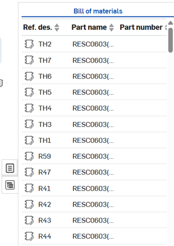
-
若要了解 BOM 表格中的某一列是代表圖形區域中的那一個零組件,請選擇一個列或是選擇零組件 - 注意到出現的交叉強調顯示:
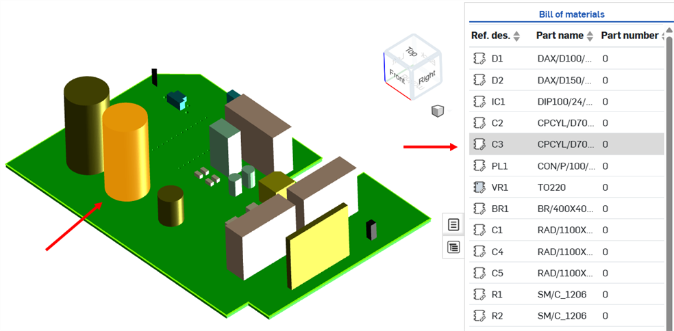
若要選取,請在圖形區域中的項目上按一下,或按一下表格中的某列。若要取消選取,再按一下項目 (於圖形區域中),按一下空白處或按一下其他項目。
如果已指定,請更新零組件的參考指標 (reference designator)。在 BOM 表格中,連按兩下零組件的參考指標 (Ref. des.) 儲存格,然後編輯其值 (如下方圖片所示)。
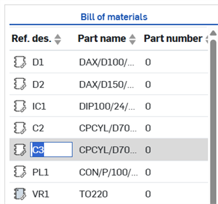
編輯參考指標 (reference designator) 值時請小心,因為並無法避免您重複另一零組件的值,或更新為不相容的值。這可能會導致 ECAD 系統的問題。
當從 Professional 或 Enterprise 計畫降為 Free 或 Standard 計畫時,並不會刪除 PCB Studio 分頁,但會無法存取。
關於「學習中心」的其他資源,請用自己的步調跟著 PCB Studio Fundamentals (需要有 Onshape 帳戶) 的課程操作。