 擠出
擠出
![]()
![]()
![]()
將深度延著一個直的路徑加入至所選區域或平坦面上。藉由加入或移除材料,或在路徑上使零件相交來建立新的零件或曲面,或是修改現有的零件或曲面。可使用「擠出」來建立零件、曲面或薄件擠出。
快速鍵:Shift+e
「擠出」特徵可讓您延著一個直的路徑加入深度至所選區域或平坦面上。藉由加入或移除材料,或在路徑上使零件相交來建立新的零件或曲面,或是修改現有的零件或曲面。可使用「擠出」來建立零件或曲面。若要建立實體,請先建立一個草圖輪廓。
按一下 Part Studio 工具列中的「擠出」特徵工具。請確定為擠出類型選擇了「實體」。接著在圖形區域中選擇草圖輪廓。選擇擠出的結果類型:「新建」、「加入」、「移除」或「相交」。選擇「終止類型」:「給定深度」、「成形至下一幾何」、「成形至面」、「成形至零件」、「成形至一頂點」或「完全貫穿」。按一下箭號來在相反的方向上擠出。
在對話方塊中輸入「深度」的測量值,或使用操控器箭頭來將深度加入草圖中。
核取「方向」並選擇一個軸或結合連接器以指定擠出的方向。
核取「起始偏移」來將擠出的開始點從草圖平面移動特定的深度。您可以設定給定深度或從圖元的偏移。按一下箭頭來將「起始偏移」反轉至相反的方向。
核取「對稱」來從所選平面的兩側擠出。僅能在「給定深度」與「完全貫穿」終止類型中使用「對稱」。
或者,與其使用「對稱」選項,改核取「第二結束位置」來指定相反的結束位置,使其深度與第一個主深度不同。
核取「拔模」來於「擠出」的操作中建立自動拔模,會以草圖平面做為中立面,並指定拔模的角度數。
按一下核取記號來接受新的「擠出」特徵。
從「草圖」或「特徵」工具列中:
- 按一下
 。
。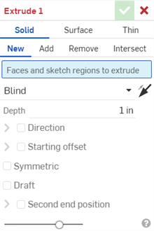
- 選擇實體建立類型。
在開啟草圖時若時選擇了擠出實體,Onshape 會自動選擇草圖中所有封閉的區域,以及嵌套式圖元 (如果有的話):
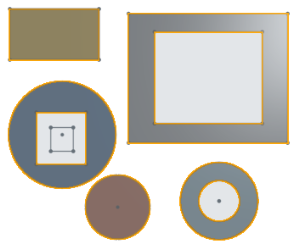
Onshape 會記住選取的項目 (實體、曲面或薄件),在後續的操作中打開對話方塊時即會有之前選取的項目。
- 選擇「結果」操作類型:
- 新建 - 建立造成新零件的新材料。
- 加入 - 建立加入至現有材料中的材料。
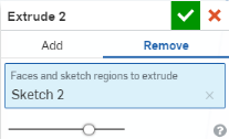
- 移除 - 將材料從零件中移除。
- 相交 - 僅留下相交存在處的材料。
- 選擇要擠出的面與草圖區域。
- 選擇一個「終止類型」:
- 給定深度 - 指定距離 (在「深度」的欄位輸入)。
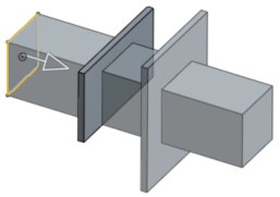
- 成形至下一幾何 - 擠出至在指定方向上所碰到的下一個面。如果無法完全地終止,則擠出會失敗。
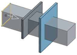
- 成形至面 - 成形至所選面或平面之下的無限面。
- 成形至零件 - 在指定的方向上成形至下一個碰到的零件或曲面。
- 成形至一頂點 - 擠出至所選的點 (頂點) 或結合連接器 (隱含或明確的)。按一下
 以選擇隱含的結合連接器。
在選擇了結合連接器之後,按一下對話方塊欄位中的「結合連接器」圖示 (下圖中以藍色輪廓線框出) 來開啟可於其中編輯結合連接器的對話方塊:
![按一下「擠出」對話方塊中的 [結合連接器] 來開啟「結合連接器」對話方塊並編輯結合](Resources/Images/sketch-tools/mateconnector-editdialog-01.png)
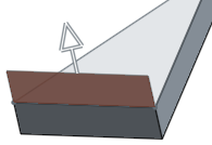
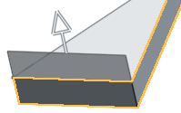
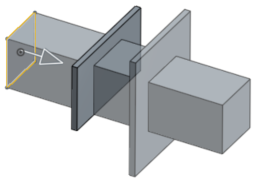
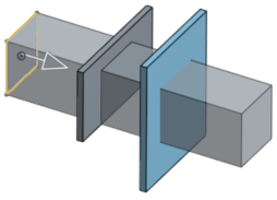
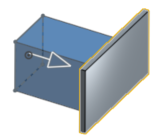
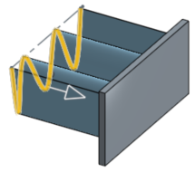
「成形至下一幾何」、「成形至面」、「成形至零件」(包括曲面)、與「成形至一頂點」都支援在一或兩個方向上的擠出偏移,如下方範例所示,會以單箭頭或雙箭頭表示:
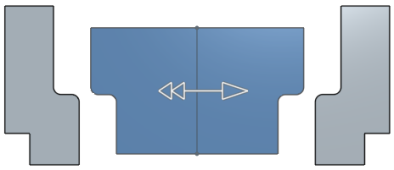
對於「成形至面」、「成形至零件」(或曲面)、與「成形至一頂點」的選項,為根據指定距離而無法到達零件、面、頂點或下一個圖元的擠出核取偏移。
- 完全貫穿 - 貫穿所有選擇的零件。
- 選擇性地指定是否要轉換至相反的方向
 。
。 - 方向 - 核取這個選項來沿著軸方向擠出。例如,垂直於草圖的一直線或結合連接器的 Z 軸:
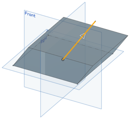
- 起始偏移 - 核取這個選項來將擠出從草圖平面偏移設定的距離。選擇一個「開始」類型:
- 給定深度 - 從指定的距離開始 (在「深度」欄位中輸入的)。
- 圖元 - 從平行於擠出圖元草圖平面的特定圖元開始。這可以是零件、面或結合連接器。按一下「結合連接器」圖示來在圖形區域中建立隱含的結合連接器,然後從該處開始擠出。
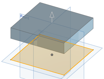
- 對稱 - 核取這個選項來在所選平面或草圖的兩側對稱擠出。僅能在「給定深度」與「完全貫穿」終止類型中使用「對稱」。
- 核取拔模來於「擠出」的操作中建立自動拔模,會以草圖平面做為中立面,並指定拔模的度數。選擇性地按一下「相反方向」圖示來反轉拔模的的方向。
- 選擇性地核取來相對於草圖平面在第二結束位置擠出。
對第二結束位置上的擠出提供所有相同的終止形態與個別的深度欄位,以及產生拔模的選項 (草圖平面做為中立面),並將拔模反轉至相反的方向。
- 輸入深度 (如有需要,為每個結束位置輸入)。
- 如果需要,選擇一個合併範圍 (或 [全部合併]) 來選擇要與新 (新增) 零件或曲面合併的零件或曲面。
- 按一下
 。
。
您可以在接受特徵 (點按核取符號) 之前使用預覽滑桿來視覺查看結果。
這個影片說明如何使用「擠出」特徵工具來從草圖輪廓建立一個曲面。
按一下 Part Studio 工具列中的「擠出」特徵工具。選擇「曲面」做為擠出類型。在圖形區域中選擇要擠出的草圖曲線。選擇擠出的結果類型:「新」或「加入」。選擇「終止類型」:「給定深度」、「成形至下一幾何」、「成形至面」、「成形至零件」、「成形至一頂點」或「完全貫穿」。按一下箭號來在相反的方向上擠出。
在對話方塊中輸入「深度」的測量值,或使用操控器箭頭來將深度加入草圖中。
核取「方向」並選擇一個軸或結合連接器以指定擠出的方向。
核取「起始偏移」來將擠出的開始點從草圖平面移動特定的深度。您可以設定給定深度或從圖元的偏移。按一下箭頭來將「起始偏移」反轉至相反的方向。
核取「對稱」來從所選平面的兩側擠出。僅能在「給定深度」與「完全貫穿」終止類型中使用「對稱」。
或者,與其使用「對稱」選項,改核取「第二結束位置」來指定相反的結束位置,使其深度與第一個主深度不同。
按一下核取記號來接受新的「擠出」特徵。
從「草圖」或「特徵」工具列中:
- 按一下
 。
。
- 選擇曲面建立類型:
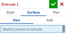
Onshape 會記住選取的項目 (實體、曲面或薄件),在後續的操作中打開對話方塊時即會有之前選取的項目。
- 選擇「結果」操作類型:
- 新 - 建立造成新零件或曲面的新材料。
- 加入 - 建立加入至現有材料中的材料。
- 選擇草圖曲線來擠出。
- 選擇一個「終止類型」:
- 給定深度 - 指定距離 (在「深度」的欄位輸入)。
- 成形至下一幾何 - 擠出至在指定方向上所碰到的下一個面。如果無法完全地終止,則擠出會失敗。
- 成形至面 - 成形至所選面或平面之下的無限面。
- 成形至零件 - 在指定的方向上成形至下一個碰到的零件或曲面。
- 成形至一頂點 - 擠出至所選的點 (頂點) 或結合連接器 (隱含或明確的)。按一下
 以選擇隱含的結合連接器。
在選擇了結合連接器之後,按一下對話方塊欄位中的「結合連接器」圖示 (下圖中以藍色輪廓線框出) 來開啟可於其中編輯結合連接器的對話方塊:
![按一下「擠出」對話方塊中的 [結合連接器] 來開啟「結合連接器」對話方塊並編輯結合](Resources/Images/feature-tools/mateconnector-editdialog-01.png)
「成形至下一幾何」、「成形至面」、「成形至零件」(或曲面)、與「成形至一頂點」都支援在一或兩個方向上的擠出偏移。下方的範例顯示「成形至下一幾何」的擠出同時有在兩個方向上 1 英吋的偏移。
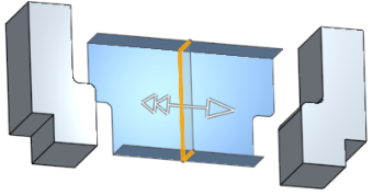
核取偏移並指定一個距離,指定的距離會導致擠出無法到達零件、面、頂點或下一個圖元。
- 完全貫穿 - 貫穿所有選擇的零件。
- 選擇性地指定是否要轉換至相反的方向
 。
。 - 方向 - 核取這個選項來沿著軸方向擠出。例如,垂直於草圖的一直線或結合連接器的 Z 軸:
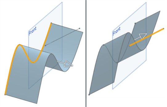
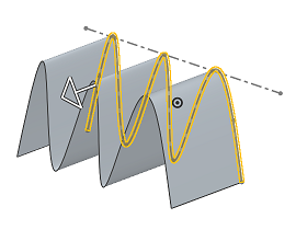
左圖是沒有選擇「方向」的曲面範例;右圖則是選取有「方向」的範例
- 起始偏移 - 核取這個選項來將擠出從草圖平面偏移設定的距離。選擇一個「開始」類型:
- 給定深度 - 從指定的距離開始 (在「深度」欄位中輸入的)。
- 圖元 - 從平行於擠出圖元草圖平面的特定圖元開始。這可以是零件、面或結合連接器。按一下「結合連接器」圖示來在圖形區域中建立隱含的結合連接器,然後從該處開始擠出。
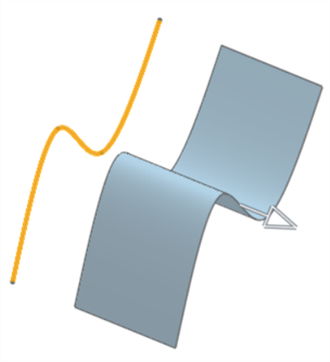
- 對稱 - 核取這個選項來在所選平面或草圖的兩側對稱擠出。僅能在「給定深度」與「完全貫穿」終止類型中使用「對稱」。
- 選擇性地核取來相對於草圖平面在第二結束位置擠出。
對第二結束位置上的擠出提供所有相同的終止形態與個別的深度欄位,以及產生拔模的選項 (草圖平面做為中立面)。
- 輸入深度 (如有需要,為每個結束位置輸入)。
- 按一下
 。
。
您可以在接受特徵 (點按核取符號) 之前使用預覽滑桿來視覺查看結果。
這個影片說明如何使用「擠出」特徵工具來從草圖輪廓建立一個薄件擠出。
按一下 Part Studio 工具列中的「擠出」特徵工具。選擇 [薄件] 做為擠出類型。在圖形區域中選擇要擠出的草圖曲線。選擇擠出的結果類型:「新」、「加入」、「移除」或「相交」。
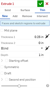
核取「中間面」選項,然後輸入「厚度」來為擠出建立對稱的厚度。
若要指定個別的壁厚,請取消核取「中間面」選項。接著輸入「厚度 1」壁厚來在一個方向上擠出指定距離。輸入「厚度 2」壁厚來在第二個相反方向上擠出指定距離。按一下「反轉壁」箭頭來將「厚度 1」與「厚度 2」反向。
選擇一個「終止類型」:「給定深度」、「成形至下一幾何」、「成形至面」、「成形至零件」、「成形至一頂點」或「完全貫穿」。按一下箭頭來在相反的方向上擠出。
在對話方塊中輸入「深度」的測量值,或使用操控器箭頭來將深度加入草圖中。
核取「起始偏移」來將擠出的開始點從草圖平面移動特定的深度。您可以設定給定深度或從圖元的偏移。按一下箭頭來將「起始偏移」反轉至相反的方向。
核取「對稱」來從所選平面的兩側擠出。僅能在「給定深度」與「完全貫穿」終止類型中使用「對稱」。
或者,與其使用「對稱」選項,改核取「第二結束位置」來指定相反的結束位置,使其深度與第一個主深度不同。
核取「拔模」來於「擠出」的操作中建立自動拔模,會以草圖平面做為中立面,並指定拔模的角度數。
從「草圖」或「特徵」工具列中:
- 按一下
 。
。
- 選擇薄件建立類型。
- 選擇「結果」操作類型:
- 新建 - 建立造成新零件的新材料。
- 加入 - 建立加入至現有材料中的材料。
- 移除 - 將材料從零件中移除。
- 相交 - 僅留下相交存在處的材料。
- 選擇要擠出的面與草圖區域。
- 可以:
- 切換開啟「中間面」,然後
- 在「厚度」欄位中指定要加入或移除的材料厚度。材料厚度會相對於所選面或曲面對稱。
- 將「中間面」維持為停用,然後:
- 指定要在第一方向 (「厚度 1」欄位) 加入或移除的材料值。可選擇性地使用「相反方向」切換來反轉方向。
- 在「厚度 2」欄位中輸入與「厚度 1」相反方向要增加或移除的材料值。
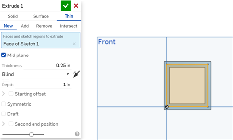
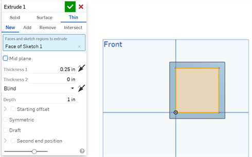
- 切換開啟「中間面」,然後
- 選擇一個「終止類型」:
- 給定深度 - 指定距離 (在「深度」的欄位輸入)。
- 成形至下一幾何 - 擠出至在指定方向上所碰到的下一個面。如果無法完全地終止,則擠出會失敗。
- 成形至面 - 成形至所選面或平面之下的無限面。
- 成形至零件 - 在指定的方向上成形至下一個碰到的零件或曲面。
- 成形至一頂點 - 擠出至所選的點 (頂點) 或結合連接器 (隱含或明確的)。按一下
 以選擇隱含的結合連接器。
在選擇了結合連接器之後,按一下對話方塊欄位中的「結合連接器」圖示 (下圖中以藍色輪廓線框出) 來開啟可於其中編輯結合連接器的對話方塊:
![按一下「擠出」對話方塊中的 [結合連接器] 來開啟「結合連接器」對話方塊並編輯結合](Resources/Images/feature-tools/extrude-thin-02.png)
「成形至下一幾何」、「成形至面」、「成形至零件」(包括曲面)、與「成形至一頂點」都支援在一或兩個方向上的擠出偏移,如下方範例所示,會以單箭頭或雙箭頭表示:

對於「成形至面」、「成形至零件」(或曲面)、與「成形至一頂點」的選項,為根據指定距離而無法到達零件、面、頂點或下一個圖元的擠出核取偏移。
- 完全貫穿 - 貫穿所有選擇的零件。
- 選擇性地指定是否要轉換至相反的方向
 。
。 - 起始偏移 - 核取這個選項來將擠出從草圖平面偏移設定的距離。選擇一個「開始」類型:
- 給定深度 - 從指定的距離開始 (在「深度」欄位中輸入的)。
- 圖元 - 從平行於擠出圖元草圖平面的特定圖元開始。這可以是零件、面或結合連接器。按一下「結合連接器」圖示來在圖形區域中建立隱含的結合連接器,然後從該處開始擠出。

- 對稱 - 核取這個選項來在所選平面或草圖的兩側對稱擠出。僅能在「給定深度」與「完全貫穿」終止類型中使用「對稱」。
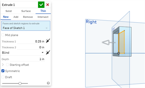
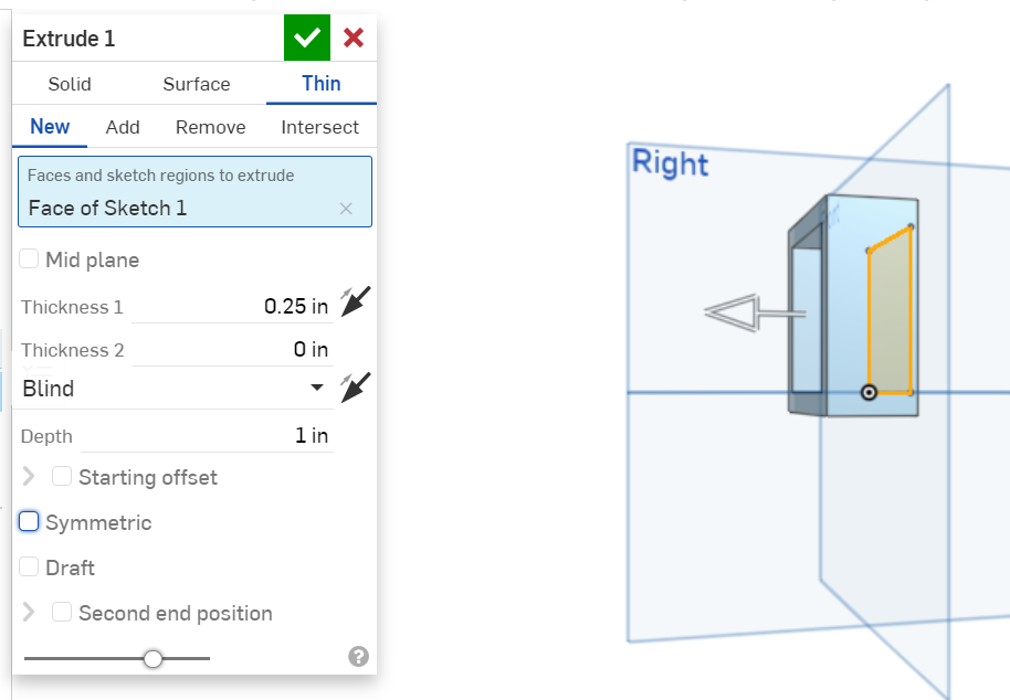
- 核取拔模來於「擠出」的操作中建立自動拔模,會以草圖平面做為中立面,並指定拔模的度數。選擇性地按一下「相反方向」圖示來反轉拔模的的方向。
- 選擇性地核取來相對於草圖平面在第二結束位置擠出。
對第二結束位置上的擠出提供所有相同的終止形態與個別的深度欄位,以及產生拔模的選項 (草圖平面做為中立面),並將拔模反轉至相反的方向。
- 輸入深度 (如有需要,為每個結束位置輸入)。
- 如果需要,選擇一個合併範圍 (或 [全部合併]) 來選擇要與新 (新增) 零件或曲面合併的零件或曲面。
- 按一下
 。
。
Onshape 會記住選取的項目 (實體、曲面或薄件),在後續的操作中打開對話方塊時即會有之前選取的項目。
在啟用了「中間面」時,「厚度 1」或「厚度 2」的「厚度」值與停用「中間面」的情況不同。在啟用與停用「中間面」的狀況之間,系統會保留這 3 欄位的值。
您可以在接受特徵 (點按核取符號) 之前使用預覽滑桿來視覺查看結果。
當在展開圖樣草圖上擠出時,會出現精簡版的擠出對話方塊,其中有在鈑金中加入或移除的選項。按一下核取記號來接受變更。
您可以在接受特徵 (點按核取符號) 之前使用預覽滑桿來視覺查看結果。
目前無法將在 3D 模型中定義的「擠出」特徵重新用為鈑金展開圖樣中的「擠出」特徵。如果嘗試這樣的操作,會出現下列的警告:
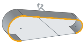
建立新材料或造成新零件或曲面的材料。
新建 - 建立造成新零件的新材料
加入 - 建立材料並加入至現有的材料中

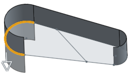
當加入材料時,您可以選擇將材料與其幾何接觸或相交的零件合併:
- 如果幾何僅與一個零件接觸或相交,則自動會將該零件加入至合併的範圍中。
- 如果多個零件與幾何接觸或相交,則有模糊的情況產生,您必須選擇要合併的零件 (合併範圍)。
- 一個選擇多個接觸或相交零件的捷徑是核取全部合併來將接觸或相交的零件加入至合併範圍中。
請注意,如果布林運算是設定為「加入」、「移除」、或「相交」,且在合併範圍內沒有設定任何項目,則特徵會有錯誤。對於「新建」的選項,因為不會對結果進行布林運算,所以不提供合併範圍。
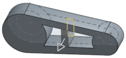
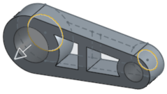
從零件中移除材料;無法在曲面中使用。
移除 - 將材料移除
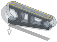
僅留下相交存在處的材料;無法在曲面中使用。
相交 - 僅留下相交存在處的材料。
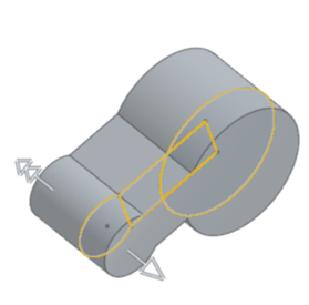
在兩個方向上相對於草圖平面不同的擠出。
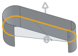
反轉擠出的第二個方向來從草圖平面建立偏移:
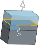
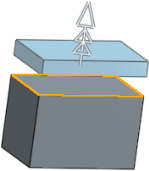
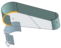
「成形至下一幾何」、「成形至面」、「成形至零件」(或曲面)、與「成形至一頂點」都支援在一或兩個方向上的擠出偏移。核取偏移距離並指定一個距離,指定的距離會導致擠出無法到達零件、面、頂點或下一個圖元。
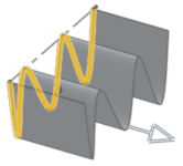
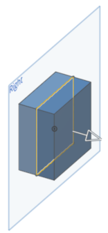
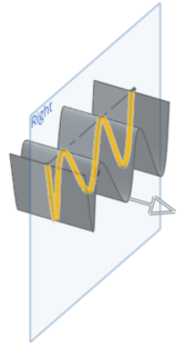
給定深度
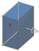
成形至在一個方向上的特定距離,或如果核取了「對稱」,會在兩個方向上以指定的距離等距擠出。
一個方向:
兩個方向 (已核取 [對稱]):
成形至下一幾何
成形至在給定方向上所碰到的下一個幾何;如果沒有碰到任何幾何,擠出除料將會失敗。請注意,被擠出的草圖範圍或圖元必須完全落在目標圖元之內,擠出才能成功
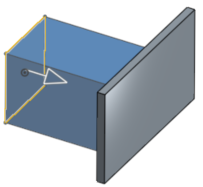
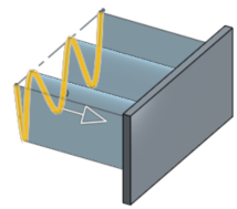
成形至面
成形至所選面或平面 (選擇一個平面或零件面) 之下的無限面;請注意,被擠出的草圖範圍或圖元必須完全落在目標圖元之內,擠出才能成功
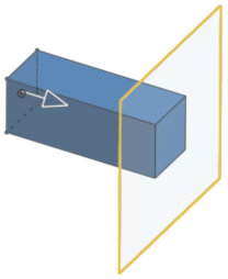
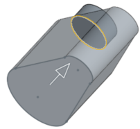
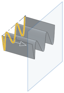
成形至零件
成形至在給定方向上所碰到的下一個零件或曲面;如果沒有碰到任何零件或曲面,擠出會失敗。請注意,被擠出的草圖範圍或圖元必須完全落在目標圖元之內,擠出才能成功。
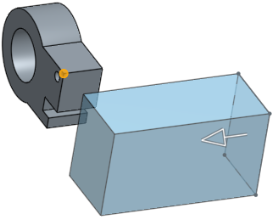
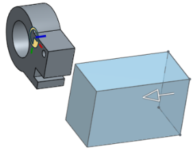
成形至一頂點
成形至所選點 (頂點) 或結合連接器 (隱含或明確的)。
完全貫穿
貫穿所有選取的零件,可以是在一個方向上也可以在兩個方向上 (已核取 [對稱])。
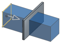
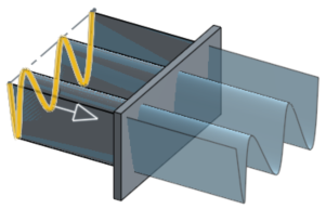
將深度延著一個直的路徑加入至所選區域或平坦面上。藉由加入或移除材料,或在路徑上使零件相交來建立新的零件或曲面,或是修改現有的零件或曲面。可使用「擠出」來建立零件、曲面或薄件擠出。
- Tap the Extrude tool icon (
 ).
).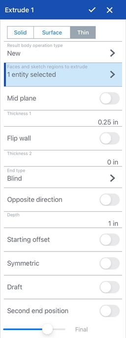
- Select Creation type:
- Solid - Create parts or modify existing parts.
- Surface - Create a surface along a sketch curve.
- Thin - Create a thin extrude along a sketch edge or face.
- 選擇一個「結果本體操作類型」:
- 新建 - 建立造成新零件的新材料。
- 加入 - 建立材料並加入至現有的材料中。
- 移除 - 將材料從零件中移除。
- 相交 - 僅留下相交存在處的材料。
- 選擇要擠出的面與草圖區域。
- 如果選取了「薄件」,可用下列方法之一選擇壁厚:
- 切換開啟「中間面」,然後
- 在「厚度」欄位中指定要加入或移除的材料厚度。材料厚度會相對於所選面或曲面對稱。
- 將「中間面」維持為停用,然後:
- 指定要在第一方向 (「厚度 1」欄位) 加入或移除的材料值。可選擇性地使用「相反方向」切換來反轉方向。
- 在「厚度 2」欄位中輸入與「厚度 1」相反方向要增加或移除的材料值。
在啟用了「中間面」時,「厚度 1」或「厚度 2」的「厚度」值與停用「中間面」的情況不同。在啟用與停用「中間面」的狀況之間,系統會保留這 3 欄位的值。
- 切換開啟「中間面」,然後
- 選擇一個「終止類型」:
- 給定深度 - 指定距離 (在深度的欄位輸入)。
- 成形至下一幾何 - 成形至在給定方向上所碰到的下一個幾何;如果沒有碰到現有的幾何,擠出除料將會失敗。
- 成形至面 - 成形至所選面或平面之下的無限面 (當選取了「成形至面」時,您可以輕觸「結合連結器」圖示來選擇或建立隱含的結合連接器)。
- 成形至零件 - 成形至在給定方向上所碰到的下一個零件 (或曲面);如果沒有碰到任何零件,擠出會失敗。
- 成形至一頂點 - 成形至所選點 (頂點) 或結合連接器 (當選取了「成形至一頂點」時,您可以輕觸「結合連結器」圖示來選擇或建立隱含的結合連接器)。
- 完全貫穿 - 貫穿所有選取的零件。
- 可選擇性指定是否要轉換至相反的方向。
- 切換方向來沿著軸方向擠出。例如,垂直於草圖的一直線或結合連接器的 Z 軸。
- 選擇性地輕觸「結合連接器」圖示以選擇或建立隱含的結合連接器。
- 切換起始偏移來將擠出從草圖平面偏移設定的距離。選擇一個「開始」類型:
- 給定深度 - 從指定的距離開始 (在「深度」欄位中輸入的)。
- 圖元 - 從平行於擠出圖元草圖平面的特定圖元開始。這可以是零件、面或結合連接器 (輕觸「結合連接器」圖示以選擇或建立隱含的結合連接器)。
- 切換開啟對稱來在所選平面或草圖的兩側對稱擠出。僅能在「給定深度」與「完全貫穿」終止類型中使用「對稱」。
- 選擇性地切換開啟拔模來於「擠出」的操作中建立自動拔模,會以草圖平面做為中立面,並可指定拔模的度數。選擇性地輕觸「相反方向」圖示來反轉拔模的的方向。
- 選擇性切換開啟第二結束位置來相對於草圖平面在第二結束位置擠出。
- 輸入深度 (如有需要,為每個結束位置輸入)。
- 輕觸核取記號。
- 在有草圖開啟的情況下,選擇擠出工具。
- Onshape 會自動選擇草圖中的所有區域。例外的情況是當有嵌套式草圖圖元存在時,Onshape 僅選擇嵌套式草圖圖元間的區域。
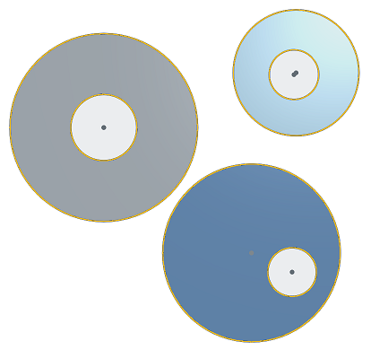
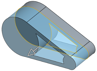
新建 - 建立造成新零件的新材料
加入 - 建立材料並加入至現有的材料中
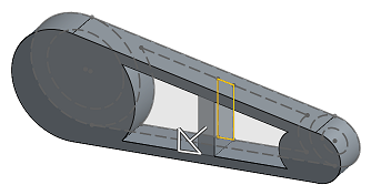
當加入材料時,您可以選擇將材料與其幾何接觸或相交的零件合併:
- 如果幾何僅與一個零件接觸或相交,則自動會將該零件加入至合併的範圍中。
- 如果多個零件與幾何接觸或相交,則有模糊的情況產生,您必須選擇要合併的零件 (合併範圍)。
- 一個選擇多個接觸或相交零件的捷徑是切換全部合併來將接觸或相交的零件加入至合併範圍中。
如果布林運算是設定為「加入」、「移除」、或「相交」,且在合併範圍內沒有設定任何項目,則特徵會有錯誤。對於「新」的選項,因為不會對結果進行布林運算,所以不提供合併範圍。
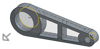
移除 - 將材料移除
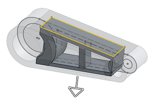
相交 - 僅留下相交存在處的材料
沿草圖曲線建立曲面。
在兩個方向上相對於草圖平面不同的擠出。
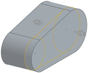
這些範例顯示的都是一個簡單零件或曲面的擠出,進而產生新的材料。
給定深度
成形至在一個方向上的特定距離,或如果核取了「對稱」,會在兩個方向上以指定的距離等距擠出。
一個方向:
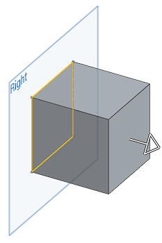
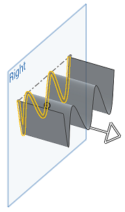
兩個方向 (已開啟 [對稱])。
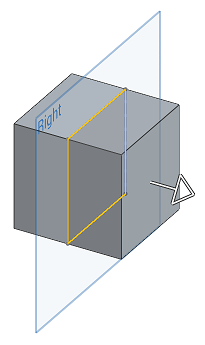
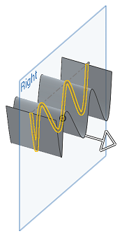
成形至下一幾何
成形至在給定方向上所碰到的下一個幾何;如果沒有碰到任何幾何,擠出除料會失敗。請注意,被擠出的草圖範圍或圖元必須完全落在目標圖元之內,擠出才能成功
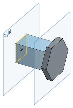
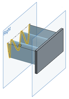
成形至面
成形至面或平面 (選擇一個平面或零件面) 之下的無限面。請注意,被擠出的草圖範圍或圖元必須完全落在目標圖元之內,擠出才能成功。
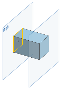
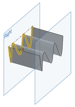
成形至零件
成形至在給定方向上所碰到的下一個零件或曲面;如果沒有碰到任何零件或曲面,擠出會失敗。請注意,被擠出的草圖範圍或圖元必須完全落在目標圖元之內,擠出才能成功。


成形至一頂點
成形至所選點 (頂點) 或結合連接器
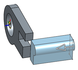
完全貫穿
貫穿所有選取的零件,可以是在一個方向上也可以在兩個方向上 (已開啟「對稱」)。
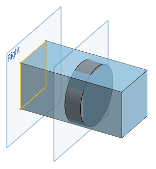
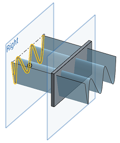
將深度延著一個直的路徑加入至所選區域或平坦面上。藉由加入或移除材料,或在路徑上使零件相交來建立新的零件或曲面,或是修改現有的零件或曲面。可使用「擠出」來建立零件、曲面或薄件擠出。
- 輕觸擠出工具。


- Select Creation type:
- Solid - Create parts or modify existing parts.
- Surface - Create a surface along a sketch curve.
- Thin - Create a thin extrude along a sketch edge or face.
- 選擇一個「結果本體操作類型」:
- 新建 - 建立造成新零件的新材料。
- 加入 - 建立材料並加入至現有的材料中。
- 移除 - 將材料從零件中移除。
- 相交 - 僅留下相交存在處的材料。
- 選擇要擠出的面與草圖區域。
- 如果選取了「薄件」,可用下列方法之一選擇壁厚:
- 切換開啟「中間面」,然後
- 在「厚度」欄位中指定要加入或移除的材料厚度。材料厚度會相對於所選面或曲面對稱。
- 將「中間面」維持為停用,然後:
- 指定要在第一方向 (「厚度 1」欄位) 加入或移除的材料值。可選擇性地使用「相反方向」切換來反轉方向。
- 在「厚度 2」欄位中輸入與「厚度 1」相反方向要增加或移除的材料值。
在啟用了「中間面」時,「厚度 1」或「厚度 2」的「厚度」值與停用「中間面」的情況不同。在啟用與停用「中間面」的狀況之間,系統會保留這 3 欄位的值。
- 切換開啟「中間面」,然後
- 選擇一個「終止類型」:
- 給定深度 - 指定距離 (在深度的欄位輸入)。
- 成形至下一幾何 - 成形至在給定方向上所碰到的下一個幾何;如果沒有碰到現有的幾何,擠出除料將會失敗。
- 成形至面 - 成形至所選面或平面之下的無限面。
- 成形至零件 - 成形至在給定方向上所碰到的下一個零件 (或曲面);如果沒有碰到任何零件,擠出會失敗。
- 成形至一頂點 - 擠出至所選的點 (頂點) 或結合連接器。
- 完全貫穿 - 貫穿所有選取的零件。
- 選擇性地指定是否要轉換至相反的方向。
- 切換方向來沿著軸方向擠出。例如,垂直於草圖的一直線或結合連接器的 Z 軸。
- 切換起始偏移來將擠出從草圖平面偏移設定的距離。選擇一個「開始」類型:
- 給定深度 - 從指定的距離開始 (在「深度」欄位中輸入的)。
- 圖元 - 從平行於擠出圖元草圖平面的特定圖元開始。這可以是零件、面或結合連接器。按一下「結合連接器」圖示來在圖形區域中建立隱含的結合連接器,然後從該處開始擠出。
- 切換開啟對稱來在所選平面或草圖的兩側對稱擠出。僅能在「給定深度」與「完全貫穿」終止類型中使用「對稱」。
- 選擇性地切換開啟拔模來於「擠出」的操作中建立自動拔模,會以草圖平面做為中立面,並可指定拔模的度數。選擇性地輕觸「相反方向」圖示來反轉拔模的的方向。
- 選擇性切換開啟第二結束位置來相對於草圖平面在第二結束位置擠出。
- 輸入深度 (如有需要,為每個結束位置輸入)。
- 輕觸核取記號。
- 在有草圖開啟的情況下,選擇擠出工具。
- Onshape 會自動選擇草圖中的所有區域。例外的情況是當有嵌套式草圖圖元存在時,Onshape 僅選擇嵌套式草圖圖元間的區域。

新建 - 建立造成新零件的新材料

加入 - 建立材料並加入至現有的材料中

當加入材料時,您可以選擇將材料與其幾何接觸或相交的零件合併:
- 如果幾何僅與一個零件接觸或相交,則自動會將該零件加入至合併的範圍中。
- 如果多個零件與幾何接觸或相交,則有模糊的情況產生,您必須選擇要合併的零件 (合併範圍)。
- 一個選擇多個接觸或相交零件的捷徑是切換全部合併來將接觸或相交的零件加入至合併範圍中。
如果布林運算是設定為「加入」、「移除」、或「相交」,且在合併範圍內沒有設定任何項目,則特徵會有錯誤。對於「新」的選項,因為不會對結果進行布林運算,所以不提供合併範圍。
移除 - 將材料移除

相交 - 僅留下相交存在處的材料

沿草圖曲線建立曲面。

在兩個方向上相對於草圖平面不同的擠出。

這些範例顯示的都是一個簡單零件或曲面的擠出,進而產生新的材料。
給定深度
成形至在一個方向上的特定距離,或如果核取了「對稱」,會在兩個方向上以指定的距離等距擠出。
一個方向:


兩個方向 (已開啟「對稱」):


成形至下一幾何
成形至在給定方向上所碰到的下一個幾何;如果沒有碰到任何幾何,擠出除料會失敗。請注意,被擠出的草圖範圍或圖元必須完全落在目標圖元之內,擠出才能成功


成形至面
成形至面或平面 (選擇一個平面或零件面) 之下的無限面。請注意,被擠出的草圖範圍或圖元必須完全落在目標圖元之內,擠出才能成功。


成形至零件
成形至在給定方向上所碰到的下一個零件 (或曲面);如果沒有碰到任何零件或曲面,擠出會失敗。請注意,被擠出的草圖範圍或圖元必須完全落在目標圖元之內,擠出才能成功。


成形至一頂點
成形至所選點 (頂點) 或結合連接器

完全貫穿
貫穿所有選取的零件,可以是在一個方向上也可以在兩個方向上 (已開啟「對稱」)。


