CAM Studios
![]()
僅為 提供。
Onshape CAM Studios 可讓您根據 CAD 模型幾何來建立切削策略或刀具路徑。這些策略會發佈為 CNC 工具機可解讀稱為 Gcode 的程式語言。CNC 工具機使用這些程式碼來操控工具機的軸與切削工具來從一塊原料中移除材料,是某種形式的減材製造。
Onshape 的 CAM Studio 提供兩種產品:CAM Studio 與 CAM Studio Advanced。CAM Studio 是包括在 Onshape Professional (或更高層級) 的訂閱中,並包括基本的刀具路徑策略與 2.5 與 3 軸選項的機器加工。CAM Studio Advanced 包括進階的刀具路徑策略與 2.5、3、4、3+2、與 5 軸的機器加工。
建立 CAM Studio
-
在 Onshape 文件中,按一下介面左下角的「插入新分頁」圖示
 。
。 -
從功能表中選擇 Create CAM Studio。新的 CAM Studio 分頁即會自動開啟。
您可以點按問號圖示來使用整個 CAM Studio 介面中的工具提示,讀取關於各種可用操作和選項的詳細資訊。
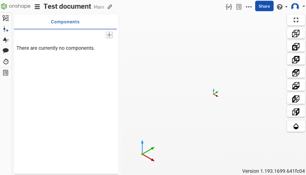
在建立「CAM Studio」分頁後會有「Components」頁面出現:
在將一個零組件加入至 CAM Studio 後,系統會將該零組件加入到介面左側的「Components」面板中。
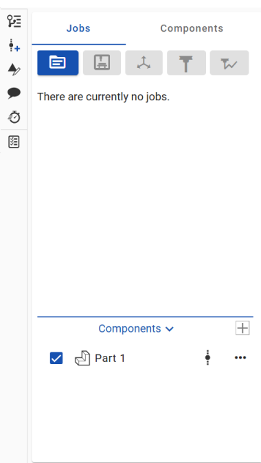
加入零組件會啟動介面最上方工具列中的「Create job」按鈕。
工具列
工具列位在介面的左側,「Jobs」與「Components」面板的上方,其中包括下列選項:
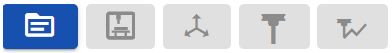
(從左至右)
-
Insert part, workholding, and stock
-
Create job
-
Create machine
-
Create setup
-
Create tool
-
Create toolpath
-
Create work plane
在下方相對應的部分讀取每個選項的具體細節。
工具列按鈕一開始不是啟用的,當您完成 CAM Studio 過程中的各步驟時會變為啟用。
檢視選項
檢視選項位在 CAM Studio 介面的右側 (下圖中以紅色輪廓線框出):
![]()
可用的選項有:
|
|
在圖形區域中將顯示的模型置中。 |
|
|
在圖形區域中以等角檢視模型 |
|
|
在圖形區域中標準的正面模型檢視 |
|
|
在圖形區域中標準的背面模型檢視 |
|
|
在圖形區域中標準的頂面模型檢視 |
|
|
在圖形區域中標準的底面模型檢視 |
|
|
在圖形區域中標準的左面模型檢視 |
|
|
在圖形區域中標準的右面模型檢視 |
|
|
將圖形區域中的零組件或模型變為透明的。 |
按一下視角圖示來在圖形區域中運用該視角。
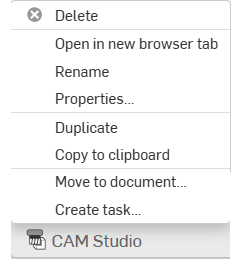
環境選單
在「CAM Studio」分頁 (Onshape 介面的底部) 上按右鍵來存取環境選單:
-
刪除 - 刪除目前的 CAM Studio (即使是使用中的)。無法刪除最後剩下的分頁。
-
在新瀏覽器分頁開啟 - 在新的瀏覽器分頁中開啟這個 CAM Studio 分頁。
-
重新命名 - 重新命名這個 CAM Studio。
-
屬性 - 存取提供更多關於 CAM Studio 資訊的「屬性」對話方塊。
-
複製 - 建立 CAM Studio 的即時副本。系統會將副本ˋ直接貼到目前的文件中,自ˋ動產生一個新的 CAM Studio 分頁。
-
複製到剪貼簿 - 將 CAM Studio 複製到您的剪貼簿中。
-
更新連結的文件 - 如果適用的話,允許您更新至所連結文件的特定版本。
-
移動至文件 - 將 CAM Studio 移動到一個新的或現有的文件中 (如果移動到新文件中,會在這個操作的過程中建立新文件)。
-
建立工作 - 建立可指派給其他使用者 (或目前使用者) 的工作,工作可參考零件並有到期日。系統會通知被指派工作的使用者關於該工作。您可以從任何 Onshape CAM Studio、Part Studio,、組合件與工程圖分頁,以及從「分頁」管理員的環境選單中建立工作。
-
在介面左側的「Components」區段中,按一下「插入」圖示下拉式清單,然後選取一種零組件類型以定義要加工的零件:
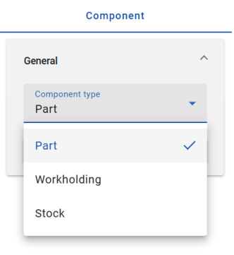
從這些選項中選擇:
Insert part - 將要加工的零組件。
Insert workholding - 在工具機中用來夾住零件的零組件 (這可以包括虎鉗、軟鉗口、壓鉗等)。
Insert stock - 經加工除料以產生零件的原材料。
這些每個選項都需要一個版本參考。
-
選擇一個零件。會將您選取的零件加入至零組件清單中以進行加工,「Insert」對話方塊會自動關閉。
-
在零組件上按右鍵來存取環境選單的選項:[隱藏]、[更新連結的文件]、[開啟連結的文件]、或 [刪除]。
-
按一下「Jobs」面板上方工具列中的 Create job 按鈕。
-
在「General」的部分輸入工作的名稱:
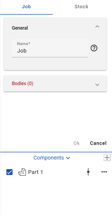
-
展開「Bodies」的部分,然後在圖形區域中選擇此工作的零件。
-
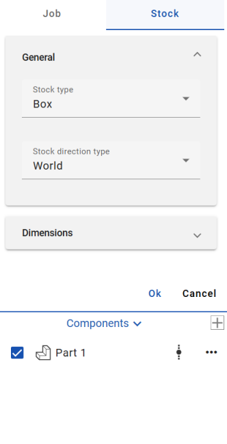
按一下此部分最上方的 [Stock] (「Jobs」的右邊) 來存取「Stock」的設定:
-
在「General」的部分:
-
從下拉選項中選擇一個「Stock type」。
Box - 定義圍繞目標模型的邊界方塊。您可以用 X、Y 與 Z 輸入值來調整原料的大小。
Cylinder - 建立圍繞目標零件可調整的圓柱原料模型。
User defined - 可讓您指定一個在 CAD 中設計的選取模型,然後匯入至 CAM Studio 來做為原料。
-
從下拉選項中選擇一個「Stock direction」:
World - 選擇模型原點做為方向類型。
Z and X - 選擇 Z 與 X 軸點做為方向類型 (在選擇此選項之後,指定原料 Z 方向與原料 X 方向)。
Z and Y - 選擇 Z 與 Y 軸點做為方向類型 (在選擇此選項之後,指定原料 Z 方向與原料 Y 方向)。
X and Y - 選擇 X 與 Y 軸點做為方向類型 (在選擇此選項之後,指定原料 X 方向與原料 Y 方向)。
-
-
展開「Dimensions」的部分,然後根據您的喜好輸入所需的參數。
-
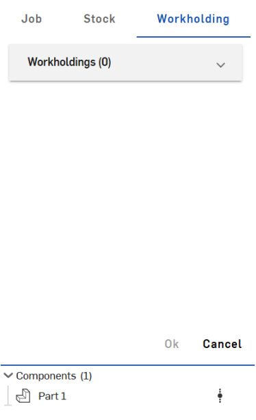
Click Workholding (to the right of Stock) at the top of the section to access the Workholding settings:
-
Expand the Workholdings dropdown and select bodies for the job.
-
按一下 [OK] 來接受。
Right-click on a component to access the context menu options: Hide, Update linked document, Open linked document, or Delete.
-
按一下「Jobs」面板上方工具列中的 Create machine 按鈕。
-
在「Machine」的部分,「Group by machine manufacturer」選項預設是開啟的。這個選項根據製造商排列工具機的清單 (相反的若是關閉選項,則會是一個長的清單):
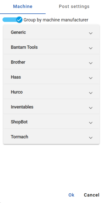
An image of the Machine section with the Group by machine manufacturer option toggled on. The Generic dropdown is open by default.
-
With Group by machine manufacturer toggled on, click through each dropdown to select a machine that the part will be machined on:
-
Generic
-
Bantam Tools
-
Brother
-
Haas
-
Hurco
-
Inventables
-
ShopBot
-
STEPCRAFT
-
Thermwood
-
Tormach
-
-
在「Post settings」的部分,根據您的喜好為後處理編輯參數。設定包括:
-
Program - 選擇輸出單位。
-
Datum - Optionally, toggle off the default Advanced work planes option.
-
NC general - 「Sequence numbering」預設是開啟的。輸入「Block number start」與「Block number increment」。選擇性地切換開啟「Block number at tools only」或「Block number as tool number」選項。
-
Movement - Optionally, toggle off the default Rapid positioning option and manually enter a Rapid rate. You can also choose to toggle on/off the following options: Output Arcs, Arcs in XY plane, Arcs in XZ plane, Arcs in YZ plane, and Output helices. Enter the number of decimal places.
-
Fixed cycles - 選擇性地切換開啟/關閉下列的選項:「Drilling canned cycles」、「Peck drilling canned cycles」、「Thread tapping canned cycles」、與「Chip break canned cycles」。
後處理器 (post processor) 是一個轉譯程式,用來將 CAM 資料轉換為特定工具機控制器類型的 Gcode。
-
-
按一下 [OK] 來接受。
Right-click on a component to access the context menu options: Hide, Update linked document, Open linked document, or Delete.
「Setup」建立工作元素的 Work Coordinate System (WCS)。工作座標系統是設定的參考點,用來建立相對於工具機座標系統的已知基準。工作座標系統定義與 CNC 工具機ˋ相關的 X、Y、與 Z 軸的原點和方位,且是所有加工操作的參考點。可以使用多個設定。
-
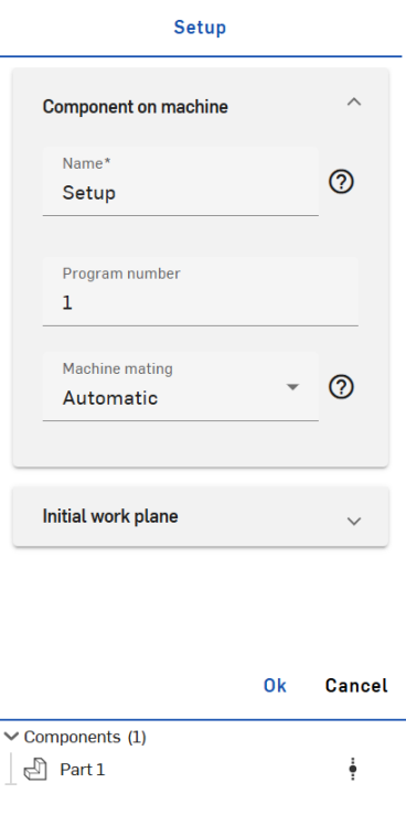
Click the Create setup button in the toolbar above the Jobs panel:
-
Fill in the parameters according to your preferences:
-
Component on machine
-
Name - Enter a name for the setup.
-
Program number - Enter a program number.
-
Machine mating - Select automatic or manual machine mating. If Manual is selected, manually enter the parameters for Offset X, Offset Y, and Offset Z. If Automatic is selected, the component will automatically move into an ideal mating position, considering the bottom area of the component mating with the machine connector. Machine mating is responsible for positioning the component (in linear terms) in machine space.
-
-
Initial work plane
-
Name - Enter a name for the work plane.
-
Work plane origin - Select a work plane origin; choose from World, Component box point, Stock box point, or Manual. Work plane origin is responsible for positioning the datum in the component.
-
Work plane orientation - Select a work plane orientation; choose from Z and X, Z and Y, or X and Y.
-
Override datum - Optionally, override the automatically assigned absolute work plane datum.
-
-
-
按一下 [OK] 來接受。
Right-click on a component to access the context menu options: Hide, Update linked document, Open linked document, or Delete.
-
按一下「Jobs」面板上方工具列中的 Create tool 按鈕。
-
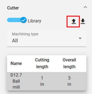
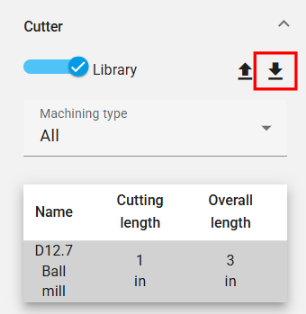
The Tool panel opens. In the Cutter section, optionally toggle the Library option on/off. While enabled, you are able to export the current tool library or import a new tool library into the CAM Studio using the import/export icons to the right of the Library toggle option. (Note, with the Library option toggled off, you are only able to import a new tool library and will have to manually enter parameters such as Machining type, Cutter type, Unit, Tool hand, Diameter, Cutting length, Overall length, and optionally toggle Center cutting on/off.)
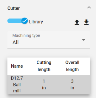
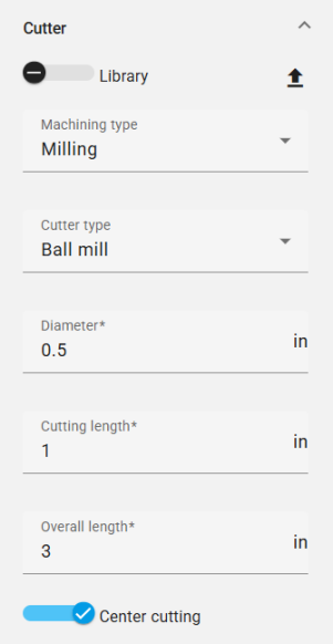
左圖是「Cutter」部分中啟用「Library」選項的螢幕擷取畫面。右圖是「Cutter」部分中關閉「Library」選項的螢幕擷取畫面。
「Machining type」的選項有:
-
All - Displays all available cutter types.
-
Milling - Displays all milling cutter types:
-
Ball mill
-
End mill
-
Bull mill
-
Dove mill
-
Lollipop mill
-
Slot mill
-
Taper mill
-
Chamfer mill
-
-
Hole making - Displays all hole making cutter types:
-
Drill
-
Thread tap tool
-
Set additional specifications for the remaining parameters:
-
Cutter type
-
Unit
-
Tool hand
-
Diameter
-
Thread direction - (only available for Thread tap tool Cutter types and is automatically synced with the Tool hand selection.)
-
Thread type - (only available for Thread tap tool Cutter types.)
-
Threads per inch - (only available for Thread tap tool Cutter types.)
-
Cutting length
-
Overall length
取決於「Machining type」,會有不同的「Cutter type」選項與組態。
-
-
在「Tool」面板的「Arbor」部分,選擇性地按一下「Enable」來使用心軸以抓住並固定刀具。當啟用時,請輸入心軸的名稱,選擇「Profile typ」,並選擇性地加入點。
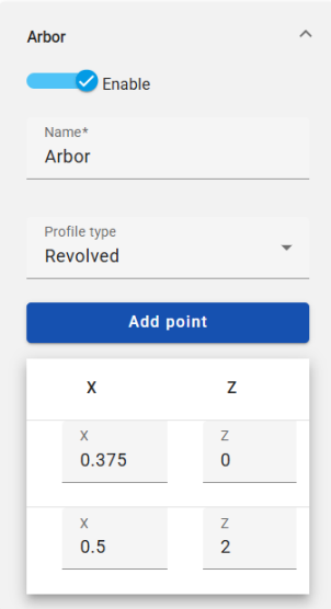
Arbor (心軸) 定義刀具的延伸類型。
-
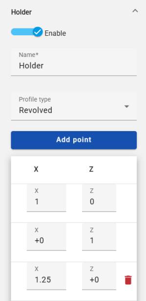
在「Tool」面板的「Holder」部分,按一下「Enable」來使用一個夾持具以固定切割刀。當啟用時,請輸入夾持具的名稱,選擇「Profile type」,並選擇性地加入或刪除點。
-
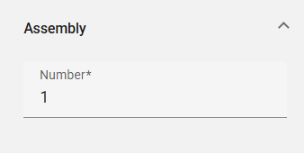
在「Tool」面板的「Assembly」部分,輸入組合件的數量。
-
按一下 [OK] 來接受。
Right-click on a component to access the context menu options: Hide, Update linked document, Open linked document, or Delete.
「Arbor」 與「Holder」定義使用 X 和 Z 值的旋轉。其資源庫允許使用者利用先前定義的資料。
匯入刀具資源庫
若要匯入一個刀具資源庫:
-
按一下在「Tool」面板的「Cutter」部分中的 Import tool library 圖示 (下圖中以紅色輪廓線框出):
-
這樣會開啟「Select tool library」對話方塊:
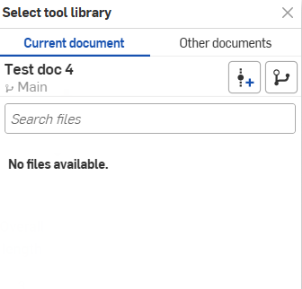
您可以直接從目前文件中匯入,或瀏覽至其他文件中來選取。
-
Optionally, click the Create version icon
 to create a version from the active document. Click the Version graph icon
  to see a version graph of the active document. Click the View released items icon
  (if applicable) to view the released items of that document.
匯出刀具資源庫
若要匯出一個刀具資源庫:
-
按一下在「Tool」面板的「Cutter」部分中的 Export tool library 圖示 (下圖中以紅色輪廓線框出):
-
刀具資源庫會匯出到文件的一個新分頁中。
-
按一下分頁來存取刀具資源庫,您可於其中更新或下載資源庫。
-
按一下「Jobs」面板上方工具列中的 Create toolpath 按鈕。
-
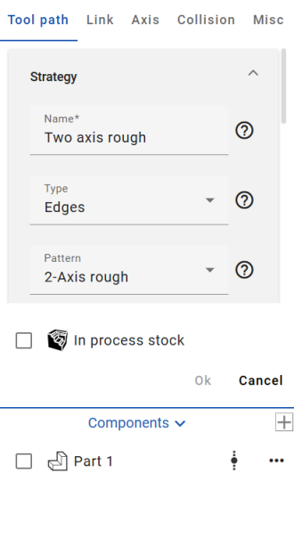
「Toolpath」設定的部分開啟:
-
在 Toolpath「Strategy」設定的部分,填入依據您喜好的參數:
Name - 輸入刀具路徑的名稱。
Type - 從可用的選項中選擇一個刀具路徑類型:
-
Edges - 根據線框輸入驅動邊線來計算刀具路徑。可作用在沒有加工面時。
-
Faces - 根據輸入驅動本體計算刀具路徑。
-
Bodies - 根據整個輸入本體計算刀具路徑。
-
Holes - Calculates toolpath based on input holes. (To choose the hole drilling order, use the Holes dropdown to enable the Select all blind holes and/or the Filter same diameter toggles.)
Pattern - 從可用的選項中選擇一個刀具路徑要依循的模式:
-
2-Axis rough - 用來快速移除大量的多餘材料。
-
2-Axis profile - 根據驅動曲線來建立刀具路徑 (驅動曲線必須是平的)。
-
2-Axis chamfer - 根據驅動曲線來建立刀具路徑,並用於倒角與去毛邊的操作中。
-
3-Axis profile - 依循驅動曲線建立刀具路徑。
-
5-Axis profile - 建立依循驅動曲線的刀具路徑,其中刀具軸是由沿者驅動曲線的方向線所控制。
-
Face - 用來加工的平坦區域 (驅動曲線必須是平的)。
-
Trochoidal - 透過擺線運動提供依序驅動曲線的加工。
-
Engrave - 沿驅動曲線加工。
Sub-pattern - 從可用的選項中選擇刀具路徑的子模式:
-
Offset - 建立從所選加工表面偏移的多個深度的多個切割。
-
Parallel - 建立在多個深度上的平行切割。
-
Adaptive - 確保切割條件幾乎保持一致 (這個策略透過不斷測量刀具與材料的接合量,並逐漸從剩餘原料中移除材料來避免全寬度的切割)。
-
選擇性地切換可啟用凹陷與凸出加工的 2.5-Axis 選項。
在檢查刀具路徑的資訊時,所有相關的參數都會顯示,以讓您組態相要的操作。當您調整參數時,系統會篩選出適用的選項。
-
-
根據您的喜好填入剩下的刀具路徑設定參數:
Drive edges - 選擇零件的邊線或曲面來定義刀具路徑的切割位置。為選取項目篩選器類型選擇「Loop」或「Contour」(請注意,當插入曲線時,無法使用 「Loop」選擇選項。您必須選擇曲線的各個線段)。
Offset - 指定留在驅動曲線上的材料量。
Step down - 指定深度步驟。
Step over - 定義刀具每次通過時水平接觸材料的程度。
Sorting - 提供「Cutting method」、「Cutting directions」、與「Machined By」的參數。
Heights - 設定「Start height type」、「Start height」、「End height type」、與「End height」。
Area - 設定「Draft angle degree」與 (選用) 切換「Close offsets」選項。
Re-machining - 提供最佳化刀具路徑的參數以減少過度切割並僅切割需要的量。
Edge containment - 將刀具路徑限制在選取的曲線之中。
Speeds - 定義不同的刀具路徑速率與方式。 設定「feed rate」、「plunge rate」、與「retract rate」的速度。啟用「rapid approach」、「rapid retract」、或「adaptive feed rate」。
Posting - 定義主軸速率與在加工過程中是否使用冷卻劑。
-
按一下「Link」部分 (「Toolpath」部分的右邊) 來存取刀具路徑的「Link」設定。根據您的喜好填入參數。
在「Clearance area」下拉的部分,「Clearance area type」指定刀具在此操作中縮回和接近的間隙區域。
在「First entry」下拉的部分,「Use ramps」選項決定刀具是否使用接近策略或直接進入材料中。
在「Ramps」下拉部分的選項取決於使用的刀具類型,切割的材料與機器的剛度。 -
按一下「Axis」部分 (「Link」部分的右邊) 來存取刀具路徑的「Axis」設定。選擇一個「Output type」,並 (選用) 啟用「Tilting」。
當啟用時,「Tilting」會定義傾斜軸。
-
按一下「Collision」部分 (「Axis」部分的右邊) 來存取刀具路徑的「Collision」設定。根據您的喜好填入參數。
「Collision」群組下拉部分的選項可修改刀具路徑縮回、修剪、與重新連結的參數,以及沿指定軸停止刀具。
-
按一下「Misc」部分 (「Collision」部分的右邊) 來存取刀具路徑的其他設定。根據您的喜好填入參數:
Profile pass - 加入一條依循驅動曲線輪廓的路徑到刀具路徑中。
Smoothing - 選擇性選取來切換下列的選項:
-
Smooth corners - 在刀具路徑的尖角處建立圓角 (請注意,不會將圓角套用到刀具路徑的外輪廓上)。
-
Smooth final pass - 在刀具路徑外輪廓的尖角處建立圓角。
-
Remove corner pegs - 自動修改切削間距並在角落加入額外的切割以去除未切割的材料。
Filtering - 選擇根據「Regions」(移除在閥值內的刀具路徑區域) 或「Contours」(移除在閥值內的刀具路徑輪廓) 來篩選。選擇「Filter type」並輸入一個 「Filter threshold value」。
Quality - 輸入一個切割公差來指定刀具路徑的精確性。這是刀具路徑相對於要加工特徵的弦偏差。
-
-
按一下 [OK] 來接受。刀具路徑會加入至「Jobs」清單中。
Right-click on a component to access the context menu options: Hide, Update linked document, Open linked document, or Delete.
Work planes are coordinate systems that can be defined in CAM Studio, and serve purposes for both machining and output-NC.
-
Click the Create work plane icon in the toolbar above the Jobs panel.
-
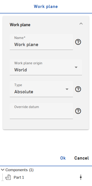
In the Work plane section:
-
Name - Enter a name for the work plane.
-
Work plane origin - Select a work plane origin; choose from World, Component box point, Stock box point, or Manual.
-
Type - Select a type for the work plane to define a method of output for toolpaths in a given work plane. Choose from the following options:
-
Absolute - The output is in a fixed datum pre-created (equally-defined) on the machine/control.
-
Dynamic - The output is in a temporary coordinate system, defined dynamically by functions such as "G68.2."
-
None - The output remains in the initial coordinate system (world), while machining/toolpaths stick to the defined work plane. (This typically does not involve transformation outputs in the generated NC.)
-
-
Override datum - Optionally, override the automatically assigned absolute work plane datum.
-
Right-click on a component to access the context menu options: Hide, Update linked document, Open linked document, or Delete.
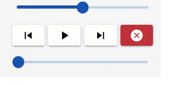
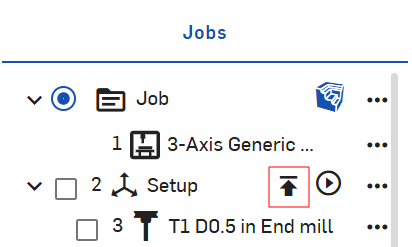
在「Jobs」部分下方,按一下操作右邊的「Preview operation」圖示來檢視「Back plot」、「Verify」、或「Simulate」。若要一次驗證或模擬所有的操作,按一下「Jobs」部分中一個設定右邊的「Preview operation」。
這會在圖形區域下方啟動預覽操作的選項:

每個選項會產生不同的結果:
Back plot - 沿刀具路徑移動刀具。
使用上方滑桿來設定動畫的速度 (左邊是最慢的,右邊是最快的)。
根據需要使用「Step back」、「Run」、「Step next」、與「Cancel」選項。
底部的滑桿代表 backplot 動畫的進度。
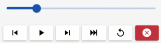
Verify - 在移除材料時,沿著刀具路徑移動刀具,可讓您進一步了解鑿痕與過度的情況,並細化處理過程中的材料 (原料)。
滑桿可設定動畫的速度 (左邊是最慢的,右邊是最快的)。
根據需要使用「Step back」、「Run」、「Step next」、「Go to end」、「Reset」、與「Cancel」選項。
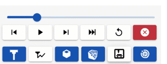
Simulate - 預覽操作。
滑桿可設定動畫的速度 (左邊是最慢的,右邊是最快的)。
根據需要使用「Step back」、「Run」、「Step next」、「Go to end」、「Reset」、與「Cancel」選項。
下方列的按鈕可切換刀具、刀具路徑、工件、原料、與工具機外殼的視覺顯示與否。
您同時有在碰撞時切換暫停的選項。
匯出
匯出操作:
-
在「Jobs」面板中,於您要匯出的設定上按右鍵來開啟環境選單,然後按一下 [Post child operations]:
Click the Post selected operations option to export only the selected operations.
-
「Export」對話方塊開啟:
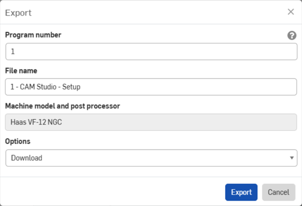
-
輸入偏好的程式編號。
-
輸入喜好的檔案名稱。
-
檢視匯出選擇的「Machine model and post processor」。
-
從下拉功能表中選擇一個下載選項:[下載]、[下載並在新分頁中存放檔案]、或 [在新分頁中存放檔案]。
-
按一下 [Export]。
關於「學習中心」的其他資源,請用自己的步調跟著 Introduction to CAM Studio (需要有 Onshape 帳戶) 的課程操作。