 剖面圖
剖面圖
![]()
![]()
![]()
在 Part Studio、組合件中提供此功能
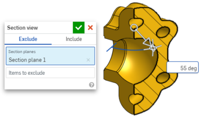
剖面視圖可讓您選擇一或多個平面、結合連接器、圓柱面或平坦面來用於剖切,也可用來選擇預設平面。可從攝影機與渲染選項功能表,或在環境選單中選擇「剖面視圖」來開啟剖面視圖。
在操控器出現之後,可以用球形 (操控器中心的空心圓) 來移動操控器,並抓取至零件、曲面或組合件中的任何推斷點。可以在 Part Studios 與組合件中檢視剖切的項目:
- 選擇零件或曲面上的一或多個平面、結合連接器、圓柱面、圓錐面或平坦面。
- 展開「攝影機與渲染選項」功能表
 ,然後選擇 剖面視圖 (如下所示)。另一個方法是在 Part Studio 中的零件或 Assembly 分頁中的組合件上按右鍵,然後從環境選單中選擇 [剖面視圖]。
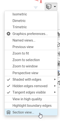
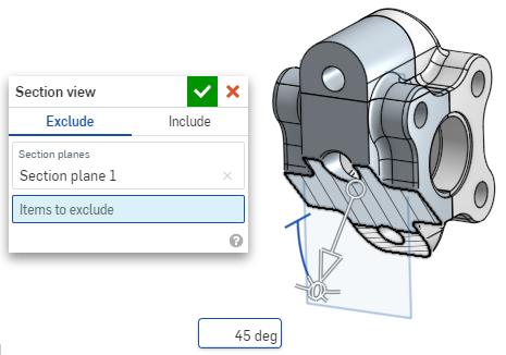
- 會在上方步驟 1 所選處剖切零件/曲面 (圓柱面、圓錐面、平坦面、平面、或結合連接器)。會有一個操控器出現在最後選取的位置,且對話方塊會開啟列出選取項目:
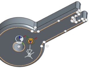
- 按一下並拖曳操控器的開放圓形 (球形) 來定位。您可以將操控器抓取至零件或組合件上的任何推斷點,包括圓柱的質心 (下方白色的標示都是推斷點):
- 使用操控器來變更剖切的深度和/或角度。
- 使用箭頭來變更深度,在不同的方向拖曳。按一下操控器來反轉視角的方向。
- 使用角度指標來某一特定角度拖曳。
- 在圖形區域中使用數值欄位來輸入視角的深度或角度。
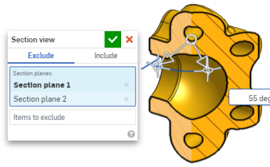
- 若要在對話方塊仍開啟時選擇一個不同的剖切平面,請為新的剖切平面在所需的位置上按一下,新的操控器與剖切平面隨即出現。
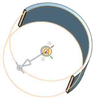
要垂直於剖切平面檢視剖面,可使用快速鍵 N,或按右鍵並從環境選單中選擇 [正視於]。
- 若要將一或多個零件 (一或多個曲面) 排除於剖切之外,請啟動「排除的項目」欄位,然後在圖形區域中選擇:
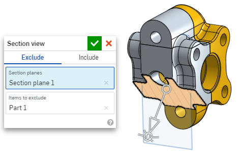
-
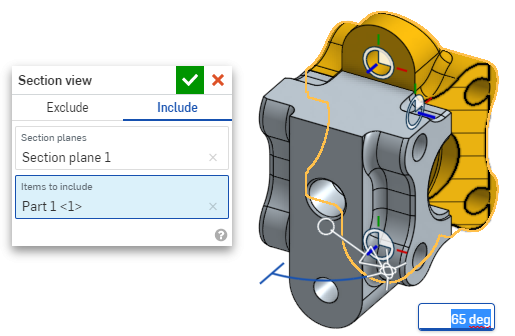
若要將一或多個零件 (一或多個曲面) 包括在剖切中,請選擇「包括」頁籤,然後在圖形區域中選擇要「包括的項目」:
若要在剖面視圖中移動模型,在對話方塊外按一下來將其關閉,然後根據需要操控模型。
- 按一下對話方塊中的「選擇預設平面」圖示
 來在圖形區域中開啟預設平面的選項:
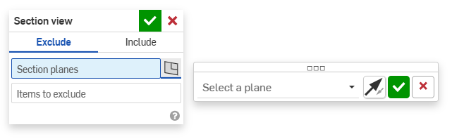
-
從下拉功能表中選擇一個預設平面,「剖面視圖」對話方塊會相對應更新。
選擇性地按一下「反轉平面」圖示來輕鬆地在前/後、上/下或右/左視角間切換。
-
按一下「選擇一個平面」選項對話方塊中的綠色核取記號來儲存並關閉預設平面選項,但 將「剖面視圖」對話方塊保持為開啟,或按一下「剖面視圖」對話方塊中的綠色核取記號 來儲存並同時關閉兩個對話方塊。
-
完成時,從「攝影機與渲染選項」功能表
或環境選單中選擇 [關閉剖面視圖] 。
您也可以在做出任何選擇之前開啟「剖面視圖」。
如果有相交的零件存在,系統會以紅色渲染。
如果沒有關閉「剖面視圖」但關閉了對話方塊,請在剖切平面上連按兩下來再次開啟對話方塊。或者是按一下「攝影機與渲染選項」功能表 ![]() ,或在零件或組合件上按右鍵來存取環境選單,然後選擇 [編輯剖面視圖]。
,或在零件或組合件上按右鍵來存取環境選單,然後選擇 [編輯剖面視圖]。
您可以使用「剖切視圖」,然後將視角儲存為命名視角。
您也可以在剖面視圖中的面、邊線和頂點上使用「測量」工具。詳細資訊請參考測量工具。