![]()
快速鍵:d
在工程圖中提供此功能
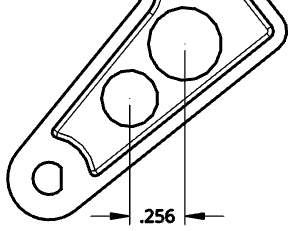
將尺寸放置在工程圖中任何類型的曲線上。
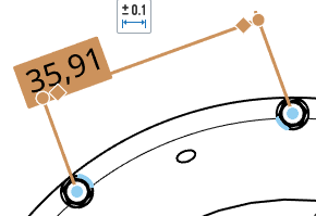
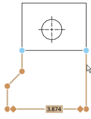
當為工程圖定義尺寸時,您會注意到將游標於直線或點上暫留時所出現的橘色抓取點。有五種類型的抓取點:
- 正方形抓取點表示端點
- 三角形抓取點表示中點
- 在圓或弧四分之一點上的菱形抓取點表示圓的四分之一
- 圓形抓取點表示弧或圓的圓心;在尺寸抓取點出現在圓或弧的圓心之後,您可以點按並將點拖曳至四分之一點。
在標註尺寸的過程中會停用中點和四分之一點,使得選擇適當的尺寸點更為容易。不過在放置尺寸之後,再次編輯尺寸即可存取這些中點和四分之一點。
使用鍵盤快速鍵 Shift+q 來為目前的指令快速地開啟中點和四分之一點。再次使用 Shift+q 即可切換為關閉。
在抓取點出現之後,則已抓取至點,然後您可以點按。一旦點出現之後,則不需要在點上直接點按。在移動滑鼠來放置尺寸的操作中,您會在游標經過靠近其他圖元時,看到細虛線的出現。這些是您可以用來對齊尺寸的推斷線;當您看到推斷線出現時只要按一下即可將尺寸與該線對齊。
若要將非常靠近的尺寸分開來,您可以使用轉折的尺寸界線。若要將轉折加入到尺寸界線上,請在尺寸界線上按右鍵來開啟環境選單,然後再按一下 [加入轉折]:
![在環境選單中強調顯示 [加入轉折] 選項的螢幕擷取畫面](../Resources/Images/drawings/addjog-contextmenu.png)
根據預設,轉折會出現在尺寸界線的中點。移動游標至尺寸線上暫留來強調顯示抓取點,然後點按並拖曳轉折尺寸界線上的抓取點至您想要的位置:
您可以標註至隱藏線的尺寸 (在使用「顯示隱藏線」指令之後)。
編輯尺寸值可能會導致尺寸轉換為重置尺寸,請參考尺寸疑難排解。
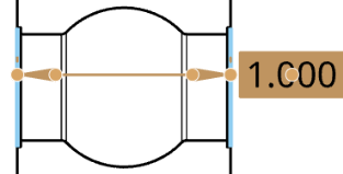
建立尺寸之後,可以將游標移動至尺寸上暫留來查看與尺寸相關的圖元。游標暫留時圖元會變為藍色:
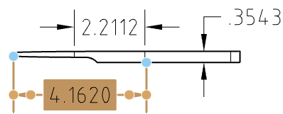
如果需要,您可以編輯現有尺寸的抓點。按一下並拖曳任何抓點至另一個邊線、點、弧、圓或圓心,會維持與其他抓點的關聯性。例如,在下方的圖示中,尺寸的右側抓點是從點被拖曳到邊線上:
只要按一下尺寸文字並拖曳,即可拖曳文字,文字上不需要有抓點。
當選取邊線時,再次點按 (即使是在標註尺寸中) 來取消選取邊線,然後選擇一條不同的邊線。
您可以變更相交尺寸線顯示的方式:相交時斷開或相交時不斷開。
在尺寸上按右鍵然後從環境選單中選擇斷開尺寸或解除斷開尺寸。只有其中一條相交線會斷開。
斷開尺寸
未斷開尺寸
您可以使用「尺寸」選擇區來自訂所選尺寸 (驅動與從動) 的外觀。選擇一個尺寸會讓尺寸選擇區圖示出現。
- 在沒有選擇工具的情況下,選擇尺寸。
- 尺寸選擇區圖示出現
 。
。 - 將游標移動至圖示上暫留來開啟選擇區 (您也可以連按兩下尺寸來開啟選擇區)。
- Set the following options in the palette:
- Above text - Enter the text or symbol to appear above the dimension value.
And then, for each of the primary dimension units and the dual dimension units, respectively:
- Prefix text - Enter the text to appear as a prefix to the dimension value.
- Count type - Use the dropdown to select a count type for the dimension.
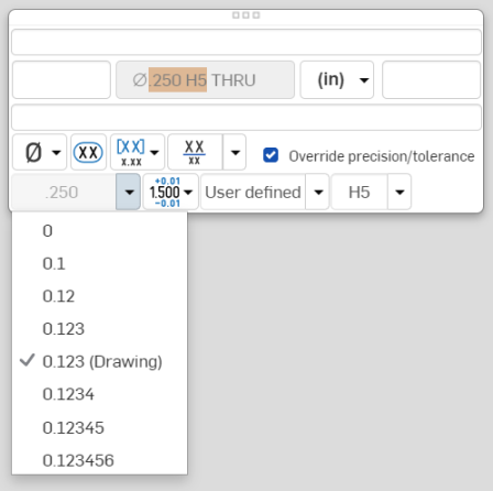
- Precision - Select the depth of unit precision (zero to 8 decimal places).
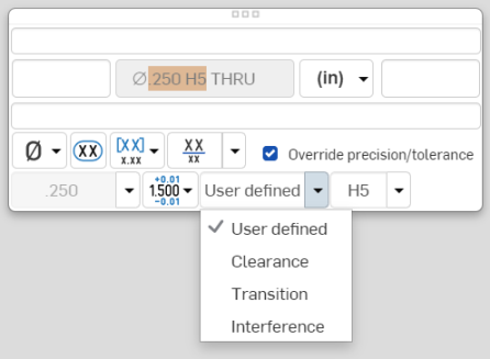
Precision defined on a drawing dimension may be linked to the Properties panel through this Dimension palette by selecting the tolerance with “(Drawing)” beside it. Whenever the Properties panel tolerance precisions are updated, any dimension with the “(Drawing)” tolerance selected will also be updated. You can choose to link these properties (and unlink them) on a dimension-by-dimension basis.
- Dimension units - Select the units of your choice. The currently selected unit is displayed in the dropdown label:
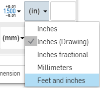
Choose from: Millimeters, Millimeters (Drawing), Centimeters, Meters, Inches, Inches fractional, Feet and inches, Feet, or Yards. This selection overrides the units for that dimension. If you later change the drawing units, the units for the dimension are not overridden. You can change the units back to (Drawing) if you want to inherit the drawing properties again.
When you choose units, you set two properties in the drawing or on a dimension - the Units property and the Fractional display property.
- Drawing units are managed separately from Workspace units for Part Studios and assemblies
- Feet and Inches is only available in drawings; it is not available for workspace units.
- Suffix text - Enter the text to appear as a suffix to the dimension value.
- Below text - Enter the text or symbol to appear below the dimension value.
- Symbol dropdown - Select a symbol to insert from the dropdown:
Symbol Name Shortcut ° Degree %%d ⌀ Diameter %%c ℄ Centerline ⌵ Countersink ↧ Depth ⌴ Counterbore □ Square ⌒ Arc length ± Plus/Minus %%p Ⓤ Unequally disposed profile Ⓘ Independency 
Continuous feature 
Spot face ▷ Translation - Inspection dimension - Toggle to add or remove an oval frame around the dimension to indicate this is an inspection dimension.
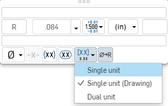
- Dual dimension - Toggle to specify whether to have a single unit dimension, single unit as specified for the drawing properties, or a dual unit dimension:
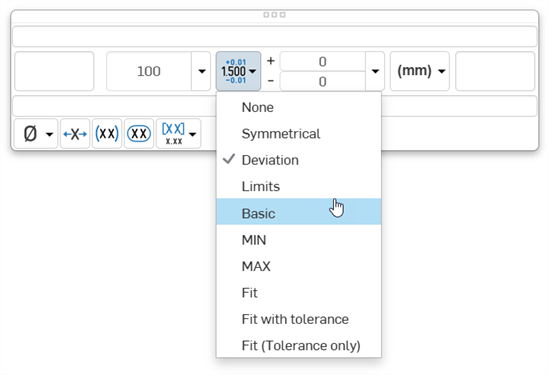
- Tolerance - Select None, Symmetrical, Deviation, Limits, Basic, MIN, MAX, Fit, Fit with tolerance, or Fit (Tolerance only).
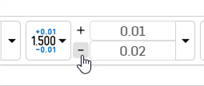
- Set the upper and lower tolerance (available for Symmetrical, Deviation, or Limits)
Optionally, to set a Deviation or Limits tolerance to plus/plus (+/+) or minus/minus (-/-), click the plus (+) or minus (-) button, as required:
- Set the Fit type, Shaft class, and Hole class (available for Fit, Fit with tolerance, or Fit (Tolerance only))
- Set the precision depth of the Fit tolerance units, from 0 to 8 decimal places (available for Fit with tolerance or Fit (Tolerance only))
- Set the upper and lower tolerance (available for Symmetrical, Deviation, or Limits)
- Reset text position - Toggle to reset the text to the previous location.
- Parentheses - Toggle to add or remove parenthesis around the dimension field.
- Toggle hole class visibility - (Available for Fit and Fit with tolerance options) Use this to show or hide the hole class in the dimension. When shown, select one of the following options:
- Stacked without line
- Stacked diagonally
- Stacked with line
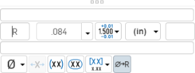
- Toggle Radius/Diameter dimension - Use this to change a radial dimension to diameter or vice versa.

您也可以在所有文字方塊、尺寸、以及註解中複製/貼上。
在選擇兩個圖元之後,會以預覽的模式提供尺寸,允許最後的放置:
- 在預覽過程中拖曳文字可以將文字移出尺寸界線外,且可以在水平、垂直與對齊測量模式間轉換:
- 將文字從兩個選擇的抓取點朝工程圖上方或下方拖曳會建立一個水平尺寸線:
- 將文字從兩個選擇的抓取點向工程圖側邊拖曳會建立一個垂直尺寸線:
- 將文字朝向垂直於直線 (穿過兩個所選抓取點) 的方向拖曳會建立一個平行於兩個所選抓取點的尺寸線:
- 同時也在文字的放置過程中提供水平與垂直的投射抓取點。這樣可讓尺寸與現有的文字/尺寸與工程圖上的其他位置對正排列:
將游標移動至符號暫留以喚醒對齊,僅在預覽模式中提供此功能。移動至其他工程圖圖元 (像是視圖的圖元) 來喚醒對齊。
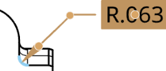
當選擇了尺寸工具時,您可以將游標移動至代表圓形邊線的邊線上以喚醒中心標記,一旦出現之後,標記會保時顯示。
當將游標移動到邊線上時,會出現一個橘色的環狀抓取點,其中有垂直的中心標記:
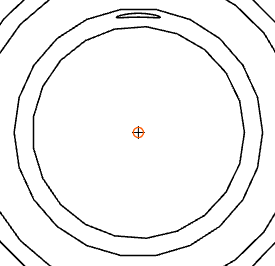
游標暫留離開之後,橘色的抓取點消失但標記仍存在:
變更尺寸箭頭的位置。可用於任何顯示有箭頭或記號的尺寸上。
當您選擇尺寸時,會在靠近尺寸箭頭或記號處顯示一個結點。按一下結點來反轉尺寸的箭頭。
反轉尺寸的箭頭:
- 在圖面區域中選擇要變更的尺寸。
- 將值拖曳至新的位置 (箭頭會相對應變更)。
在任何尺寸上點按滑鼠右鍵來開啟環境選單以存取該尺寸的指令選項清單。下方列出這些指令選項。請注意,列於此處的各種指令並不適用於所有的尺寸類型。
-
編輯 - 開啟尺寸選擇區來編輯尺寸。
-
貼上 - 將視圖中的尺寸貼到目前的位置上。
-
清除選取項目 - 取消選取所選的尺寸。
-
縮放至適當比例 - 縮放整個工程圖以配合圖面。
-
刪除 - 刪除所選的尺寸。
您可能會碰到的一些問題包括:
- 懸置尺寸 - 斷開關聯的尺寸會以紅色顯示。拖曳尺寸抓取點來將其與幾何重新關聯。詳細資訊請參考懸置圖元。
- 重置尺寸 - 有文字值的尺寸被轉換為一個無關聯的註記。重置尺寸的文字會帶有底線。編輯尺寸的尺寸值可能會導致其被轉換為重置尺寸,像是:
- 當重ˊˋ置尺寸時,您仍可以編輯尺寸面板中的其他欄位。
- 您可以刪除尺寸值欄位中的字元並結束面板來將重置尺寸恢復為關聯的尺寸。
- 在工程製圖中帶底線的尺寸值表示不是比例值。