CAM Studio
![]()
仅适用于.
Onshape CAM Studio 允许您根据 CAD 模型几何图元创建切割策略或切割路径。这些策略以一种名为 Gcode 的语言发布,由 CNC 机床进行解释。CNC 机床使用此代码来操作机床轴和切割刀具,以从库存中去除材料,以此作为差集制造的一种形式。
Onshape 的 CAM Studio 有两个产品:CAM Studio 和 CAM Studio Advanced。CAM Studio包含在 Onshape Professional(或更高版本)订阅中,包括 2.5 和 3 轴加工的基本刀具路径策略和选项。CAM Studio Advanced 包括 2.5、3、4、3+2 和 5 轴加工的高级刀具路径策略和选项。
创建 CAM Studio
-
在 Onshape 文档中,单击界面左下角的“插入新选项卡”图标
 。
。 -
从菜单中选择“创建 CAM Studio”。新的 CAM Studio 选项卡会自动打开。
您可以通过单击问号图标来使用整个 CAM Studio 界面的刀具提示,阅读有关各种可用操作和选项的更多信息。
创建 CAM Studio 选项卡后,将出现零部件页面:
向 CAM Studio 添加零部件后,该零部件将添加到界面左侧的零部件面板中。
添加零部件会激活界面顶部工具栏中的“创建作业”按钮。
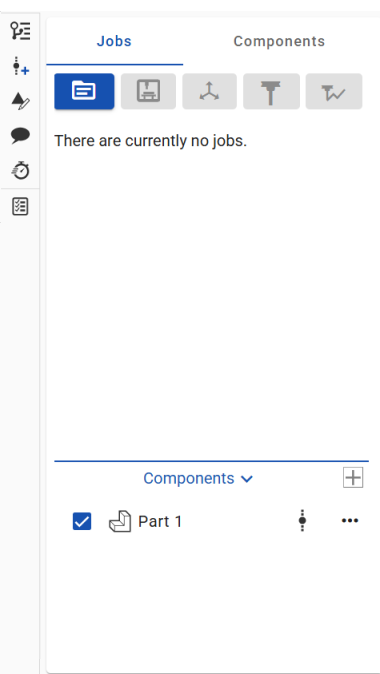
工具栏
工具栏位于界面左侧,“作业和零部件”面板上方,包括以下选项:
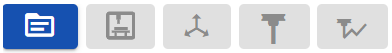
(从左到右)
-
Insert part, workholding, and stock
-
创建作业
-
创建机床
-
创建设置
-
创建刀具
-
创建刀具路径
-
Create work plane
在下面的相应部分中阅读有关每个选项的具体详细信息。
工具栏按钮开始时处于非活动状态,并在您完成 CAM Studio 流程中的步骤时变为活动状态。
视图选项
视图选项位于 CAM Studio 界面的右侧(如下图以红色勾勒):
![]()
可用的选项有:
|
|
将可见模型置于图形区域的中心位置。 |
|
|
在图形区域中以等轴方式查看模型。 |
|
|
图形区域中模型的标准正面视图。 |
|
|
图形区域中模型的标准背面视图。 |
|
|
图形区域中模型的标准正面视图。 |
|
|
图形区域中模型的标准底部视图。 |
|
|
图形区域中模型的标准左向视图。 |
|
|
图形区域中模型的标准右向视图。 |
|
|
使图形区域中的零部件或模型透明。 |
单击视图图标可在图形区域中实现该视图。
环境菜单
右键单击 CAM Studio 标签(位于 OnShape 界面的底部)以访问环境菜单:
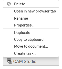
-
删除 - 删除当前 CAM Studio(即使它处于活动状态)。最后剩下的选项卡无法删除。
-
在新浏览器选项卡中打开 - 在新浏览器中打开此 CAM Studio 选项卡。
-
重命名 - 重命名此 CAM Studio。
-
特性 - 访问“特性”对话框以提供有关 CAM Studio 的更多信息。
-
复制 - 立即复制 CAM Studio。副本直接粘贴到当前文档中,自动创建新的 CAM Studio 选项卡。
-
复制到剪贴板 - 将 CAM Studio 复制到您的剪贴板。
-
更新链接文档 - 允许您更新到链接文档的指定版本(如适用)。
-
移至文档 - 将 CAM Studio 移至新文档或现有文档。(如果移动到新文档,则将在此操作期间创建新文档。)
-
创建任务 - 创建可分配给其他用户(或当前用户)的任务,此任务可参考零件并具有截止日期。被指定完成此任务的用户会收到该任务的通知。您可以从任何 Onshape CAM Studio、Part Studio、“装配体”和“工程图”选项卡创建任务,也可以从“选项卡管理器”,通过列表中的某个选项卡的环境菜单创建任务。
-
在界面左侧的“零部件”部分,单击“插入”图标下拉列表,然后选择一种零部件类型来定义要加工的零件:
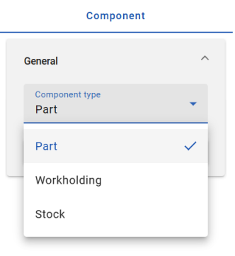
从以下选项中选择:
插入零件 - 将要加工的零部件。
插入工件夹具 - 用于将零件固定在机床上的零部件。(这可能包括虎钳、软钳口、压紧夹具等。)
插入库存 - 将加工出来生产零件的原材料。
每个选项都需要版本参考。
-
选择零件。您选择的零件将添加到零部件列表中进行加工,“插入”对话框将自动关闭。
-
右键单击组件可访问上下文菜单选项:隐藏、更新链接的文档、打开链接的文档或删除。
-
单击“作业”面板上方工具栏中的“创建作业”按钮。
-
在“常规”部分中,输入作业的名称:
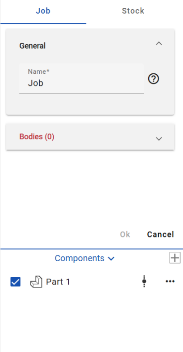
-
展开“主体”部分,然后在图形区域中为作业选择零件。
-
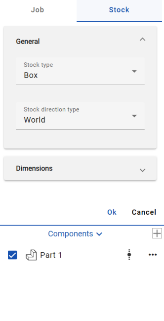
单击分区顶部的库存(“作业”右侧)以访问“库存设置”:
-
在“常规”部分:
-
从下拉选项中选择“库存类型”。
方框 - 定义目标模型周围的界限方框。您可以使用 X、Y 和 Z 输入调整库存大小。
气缸 - 围绕目标零件创建可调整的圆柱形毛坯模型。
用户已定义 - 允许您将在 CAD 中设计并导入到 CAM Studio 的选定零部件指定为库存。
-
从下拉选项中选择“库存方向类型”:
世界 - 为方向类型选择模型原点。
Z 和 X - 为方向类型选择 Z 和 X 轴点。(选择后指定库存 Z 方向和库存 X 方向。)
Z 和 Y - 为方向类型选择 Z 和 Y 轴点。(选择后指定库存 Z 方向和库存 Y 方向。)
X 和 Y - 为方向类型选择 X 和 Y 轴点。(选择后指定库存 X 方向和库存 Y 方向。)
-
-
展开“尺寸”部分,根据您的偏好输入所需的参数。
-
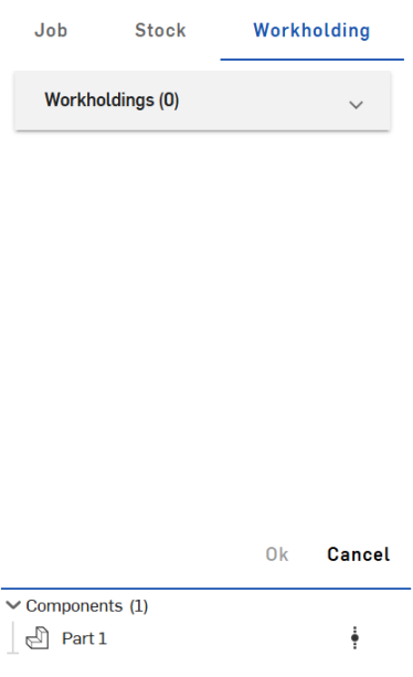
Click Workholding (to the right of Stock) at the top of the section to access the Workholding settings:
-
Expand the Workholdings dropdown and select bodies for the job.
-
单击“确定”以接受。
Right-click on a component to access the context menu options: Hide, Update linked document, Open linked document, or Delete.
-
单击“作业”面板上方工具栏中的“创建机床”按钮。
-
在“机床”部分中,“按机床制造人分组”选项默认处于启用状态。此选项按制造人整理机床列表(如果禁用该选项,则清单会很长):
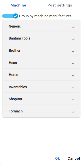
An image of the Machine section with the Group by machine manufacturer option toggled on. The Generic dropdown is open by default.
-
With Group by machine manufacturer toggled on, click through each dropdown to select a machine that the part will be machined on:
-
Generic
-
Bantam Tools
-
Brother
-
Haas
-
Hurco
-
Inventables
-
ShopBot
-
STEPCRAFT
-
Thermwood
-
Tormach
-
-
在“发布设置”部分中,根据您的喜好编辑发布的参数。这些设置是:
-
计划 - 选择输出单位。
-
Datum - Optionally, toggle off the default Advanced work planes option.
-
NC 常规 - 默认情况下,序列编号处于启用状态。输入区块编号的起始值和区块编号的增量。或者,在仅在刀具处打开“区块编号”或“区块编号作为刀具编号”选项。
-
Movement - Optionally, toggle off the default Rapid positioning option and manually enter a Rapid rate. You can also choose to toggle on/off the following options: Output Arcs, Arcs in XY plane, Arcs in XZ plane, Arcs in YZ plane, and Output helices. Enter the number of decimal places.
-
固定循环 - 可选,开启/关闭以下选项:钻孔固定循环、Peck 钻孔固定循环、螺纹攻丝固定循环和断屑固定循环。
发布或发布处理器是用于将 CAM 数据转换为特定机床控制器类型的 Gcode 的转换器。
-
-
单击“确定”以接受。
Right-click on a component to access the context menu options: Hide, Update linked document, Open linked document, or Delete.
“设置”为作业元素建立工作坐标系 (WCS)。工作坐标系是设置的参考点,用于建立相对于机床坐标系的已知基准。它定义了与 CNC 机床相关的 X、Y 和 Z 轴的原点和方向,它是所有加工操作的参考点。可以使用多种设置。
-
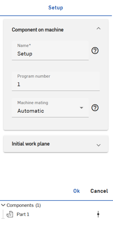
Click the Create setup button in the toolbar above the Jobs panel:
-
Fill in the parameters according to your preferences:
-
Component on machine
-
Name - Enter a name for the setup.
-
Program number - Enter a program number.
-
Machine mating - Select automatic or manual machine mating. If Manual is selected, manually enter the parameters for Offset X, Offset Y, and Offset Z. If Automatic is selected, the component will automatically move into an ideal mating position, considering the bottom area of the component mating with the machine connector. Machine mating is responsible for positioning the component (in linear terms) in machine space.
-
-
Initial work plane
-
Name - Enter a name for the work plane.
-
Work plane origin - Select a work plane origin; choose from World, Component box point, Stock box point, or Manual. Work plane origin is responsible for positioning the datum in the component.
-
Work plane orientation - Select a work plane orientation; choose from Z and X, Z and Y, or X and Y.
-
Override datum - Optionally, override the automatically assigned absolute work plane datum.
-
-
-
单击“确定”以接受。
Right-click on a component to access the context menu options: Hide, Update linked document, Open linked document, or Delete.
-
单击“作业”面板上方工具栏中的“创建工具”图标。
-
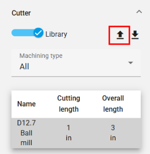
The Tool panel opens. In the Cutter section, optionally toggle the Library option on/off. While enabled, you are able to export the current tool library or import a new tool library into the CAM Studio using the import/export icons to the right of the Library toggle option. (Note, with the Library option toggled off, you are only able to import a new tool library and will have to manually enter parameters such as Machining type, Cutter type, Unit, Tool hand, Diameter, Cutting length, Overall length, and optionally toggle Center cutting on/off.)
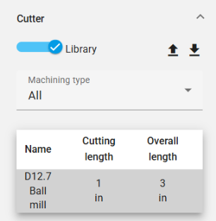
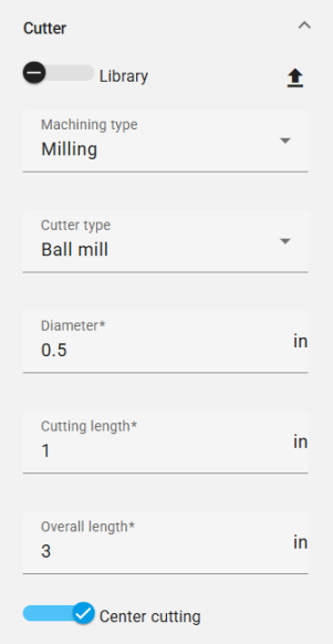
左侧是启用“库”选项的“刀具”部分的屏幕截图。在右侧,切刀部分的屏幕截图已关闭 “图库” 选项。
加工类型选项为:
-
All - Displays all available cutter types.
-
Milling - Displays all milling cutter types:
-
球型铣刀
-
端面铣刀
-
圆鼻铣刀
-
鸠尾铣刀
-
糖球铣刀
-
槽铣刀
-
锥形铣刀
-
倒角铣刀
-
-
Hole making - Displays all hole making cutter types:
-
钻孔
-
螺纹攻丝刀具
-
Set additional specifications for the remaining parameters:
-
Cutter type
-
Unit
-
Tool hand
-
Diameter
-
Thread direction - (only available for Thread tap tool Cutter types and is automatically synced with the Tool hand selection.)
-
Thread type - (only available for Thread tap tool Cutter types.)
-
Threads per inch - (only available for Thread tap tool Cutter types.)
-
Cutting length
-
Overall length
“刀具类型”选项和配置因“加工类型”而异。
-
-
在“铣刀杆”部分下方的刀具面板中,可以选择单击“启用”以使用“铣刀杆”来固定和保护刀具。启用后,输入“铣刀杆”的名称,选择“轮廓类型”,并根据需要添加点。
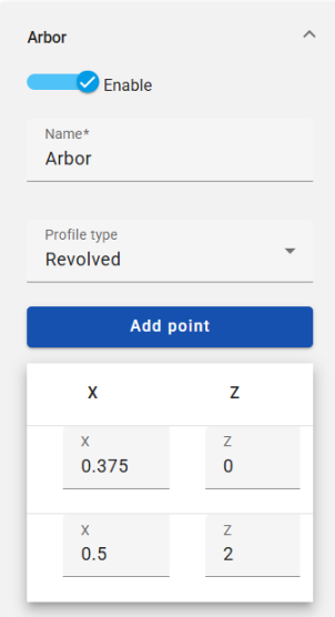
“铣刀杆”定义刀具扩展类型。
-
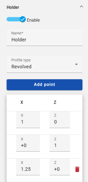
在“支架”部分下方的“刀具”面板中,单击“启用”以使用支架固定刀具。启用后,输入“支架名称”,选择“轮廓类型”,并根据需要添加或删除点。
-
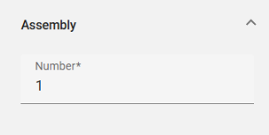
在“装配体”部分下的“刀具”面板中,输入多个装配体。
-
单击“确定”以接受。
Right-click on a component to access the context menu options: Hide, Update linked document, Open linked document, or Delete.
“铣刀杆”和“支架”使用 X 和 Z 值定义一个旋转。他们的库允许用户使用先前定义的库。
导入刀具库
要导入刀具库,请执行以下操作:
-
单击“工具”面板的“刀具”部分中的“导入工具库”图标(如下图以红色勾勒):
-
这将打开“选择刀具库”对话框:
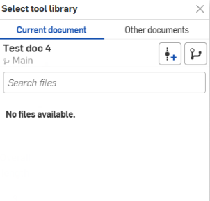
您可以直接从当前文档导入,也可以浏览其他文档进行选择。
-
Optionally, click the Create version icon
 to create a version from the active document. Click the Version graph icon
  to see a version graph of the active document. Click the View released items icon
  (if applicable) to view the released items of that document.
导出刀具库
要导出刀具库,请执行以下操作:
-
单击“工具”面板“刀具”部分中的“导出工具库”图标(如下图,以红色勾勒):
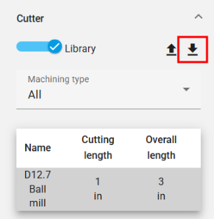
-
刀具库将导出到文档的新选项卡中。
-
单击选项卡访问刀具库,您可以在其中更新或下载该库。
-
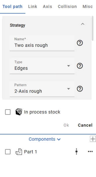
单击“作业”面板上方工具栏中的“创建工具路径”图标。
-
“刀具路径设置”部分打开:
-
在“刀具路径策略设置”部分,根据您的偏好填写参数:
名称 - 输入刀具路径的名称。
类型 - 从可用选项中选择一种刀具路径类型:
-
边 - 根据线框输入驱动边计算刀具路径。它无需任何加工面即可工作。
-
面 - 根据输入驱动主体计算刀具路径。
-
主体 - 根据整个输入主体计算工具路径。
-
Holes - Calculates toolpath based on input holes. (To choose the hole drilling order, use the Holes dropdown to enable the Select all blind holes and/or the Filter same diameter toggles.)
阵列 - 从可用选项中选择刀具路径要遵循的阵列:
-
2 轴粗加工 - 用于快速清除大量多余材料。
-
2 轴轮廓 - 根据驱动曲线创建刀具路径。(驱动曲线将展平。)
-
2 轴倒角 - 根据驱动曲线创建刀具路径,用于倒角和去毛刺操作。
-
3 轴轮廓 - 创建遵循驱动曲线的刀具路径。
-
5 轴轮廓 - 创建遵循驱动曲线的刀具路径,其中刀具轴由沿驱动曲线的方向线控制。
-
面 - 用于加工平坦区域。(驱动曲线必须是平坦的。)
-
摆线 - 通过摆线运动提供顺序驱动曲线加工。
-
雕刻 - 沿着驱动曲线的机床。
子阵列 - 从可用选项中为刀具路径选择子阵列:
-
偏移 - 在多个深度上创建多个切口,这些切口将与选定的加工曲面偏移。
-
平行 - 在多个深度上创建平行切口。
-
自适应 - 确保切割条件几乎保持不变。(这种策略通过不断测量刀具与材料的接合量来避免全角切割,并逐渐从剩余的毛坯中去除材料。)
-
或者,切换 2.5 轴选项,该选项允许加工型腔和凸台。
检查刀具路径信息时,会显示用于配置所需操作的所有相关参数。当您调整参数时,适用的选项将筛选掉。
-
-
根据您的偏好填写其余刀具路径设置参数:
驱动边 - 选择零件的边或曲面以定义刀具路径的切割区域。筛选器类型选择“循环”或“轮廓”。(请注意,插入曲线时无法使用循环选择选项。您必须选择曲线的各个线段。)
偏移 - 指定在驱动曲线上保留的材料数量。
步深 - 指定每步深度。
步距 - 定义刀具在每次走刀时水平接触材料的程度。
排序 - 提供切割方法、切割方向和加工方式的参数。
高度 - 设置“起始高度类型”、“起始高度”、“端点高度类型”和“端点高度”。
区域 - 设置拔模角度和(可选)切换闭合偏移选项。
重新加工 - 提供用于优化刀具路径的参数,以减少切削过度并仅切割所需部件。
边缘封闭 - 将刀具路径限制在选取的曲线内。
速度 - 定义各种刀具路径速率和方法。设置进给速率、切入速率和退回速率的速度。支持快速接近、快速退回或自适应进给速度。
发布 - 定义主轴速度以及在加工过程中是否使用冷却液。
-
单击“链接”部分(位于“刀具路径”部分的右侧)以访问刀具路径链接设置。根据您的偏好填写参数。
在“间隙区域”下拉列表部分下,“间隙区域类型”指定刀具在此操作中退回和接近的间隙区域。
在“第一个条目”下拉列表部分下,“使用斜坡”选项确定该刀具是利用靠近策略还是直接给进材料。
“斜坡”下拉列表部分中的选项取决于所用刀具的类型、切割的材料和机床刚度。 -
单击“轴”部分(“链接”部分的右侧)以访问“刀具路径轴”设置。选择输出类型,然后(可选)启用“倾斜”。
启用后,“倾斜”定义倾斜轴。
-
单击“碰撞”部分(“轴”部分的右侧)以访问刀具路径碰撞设置。根据您的偏好填写参数。
“碰撞组”下拉列表部分可以选择使用退回、修剪和重新链接以及沿指定轴停止刀具的参数修改刀具路径。
-
单击“其他”部分(碰撞部分的右侧)以访问刀具路径其他设置。根据您的喜好填写参数:
轮廓刀路 - 向刀具路径添加一条路径,该路径遵循驱动曲线的轮廓。
平滑 -(可选)选择切换以下选项:
-
平滑拐角 - 在刀具路径的拐角处创建圆角。(请注意,圆角不会应用于刀具路径的外部轮廓。)
-
平滑最终刀路 - 在刀具路径外部轮廓的拐角处创建圆角。
-
移除角钉 - 自动修改步距并在拐角处添加额外的切口以移除未切割的材料。
筛选 - 选择按“区域”(移除阈值内的刀具路径区域)或“轮廓”(移除阈值范围内的刀具路径轮廓)筛选。选择“筛选器类型”并输入筛选器阈值。
质量 - 输入切割公差以指定刀具路径的精度。它是刀具路径与待加工特征的弦偏差。
-
-
单击“确定”以接受。刀具路径将添加到“作业”列表中。
Right-click on a component to access the context menu options: Hide, Update linked document, Open linked document, or Delete.
Work planes are coordinate systems that can be defined in CAM Studio, and serve purposes for both machining and output-NC.
-
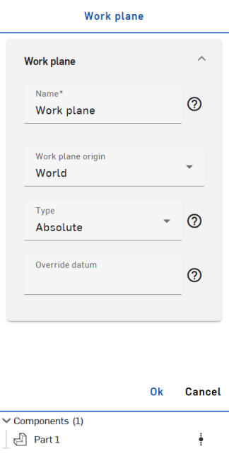
Click the Create work plane icon in the toolbar above the Jobs panel.
-
In the Work plane section:
-
Name - Enter a name for the work plane.
-
Work plane origin - Select a work plane origin; choose from World, Component box point, Stock box point, or Manual.
-
Type - Select a type for the work plane to define a method of output for toolpaths in a given work plane. Choose from the following options:
-
Absolute - The output is in a fixed datum pre-created (equally-defined) on the machine/control.
-
Dynamic - The output is in a temporary coordinate system, defined dynamically by functions such as "G68.2."
-
None - The output remains in the initial coordinate system (world), while machining/toolpaths stick to the defined work plane. (This typically does not involve transformation outputs in the generated NC.)
-
-
Override datum - Optionally, override the automatically assigned absolute work plane datum.
-
Right-click on a component to access the context menu options: Hide, Update linked document, Open linked document, or Delete.
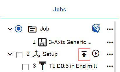
在“作业”部分下,单击操作右侧的预览操作图标以查看“背面图”、“验证”或“仿真”。(要同时验证或模拟所有操作,请单击“作业”部分中设置右侧的“预览”操作。)
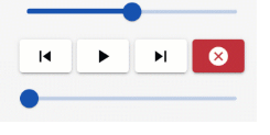
这将激活图形区域底部的预览操作选项:

每个操作都会产生不同的结果:
背面图 - 沿刀具路径移动刀具。
使用顶部滑动条设置动画的速度(左侧最慢,右侧最快)。
根据需要使用“后退”、“运行”、“下一步”和“取消”选项。
底部的滑动条表示背面图动画的进度。
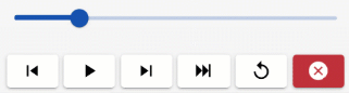
验证 - 沿刀具路径移动刀具,同时去除材料,使您能够了解更多关于缺口和多余材料的信息,并优化加工中的材料(毛坯)。
滑动条设置动画的速度(左侧最慢,右侧最快)。
根据需要使用“后退”、“运行”、“下一步”、“转到结束”、“重置”和“取消”选项。
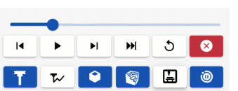
仿真 - 预览操作。
滑动条设置动画的速度(左侧最慢,右侧最快)。
根据需要使用“后退”、“运行”、“下一步”、“转到结束”、“重置”和“取消”选项。
底行按钮可打开和关闭刀具、刀具路径、工件、毛坯和机床外壳的视觉效果。
您还可以选择在碰撞时切换暂停。
导出
要导出操作:
-
在“作业”面板中,右键单击要导出的设置以打开环境菜单,然后单击“发布子操作”:
Click the Post selected operations option to export only the selected operations.
-
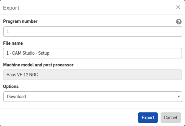
“导出”对话框打开:
-
根据需要输入程序编号。
-
根据需要输入文件名。
-
查看为导出所选定的机器模型和后处理器。
-
从下拉菜单中选择下载选项:下载、下载文件并将其存储在新的页签中,或在新页签中存储文件。
-
单击“导出”。
如需其他学习中心资源,请按此处的自定进度课程进行学习:CAM Studio 简介(需要 Onshape 帐户)