![]()
快捷键:d
可用于:工程图
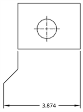
将尺寸放置在工程图中任意类型的曲线上。
定义工程图的尺寸时,您会注意到,将光标悬停在线或点上方时,会出现橙色的捕捉点。共有 5 种类型的捕捉点:
- 正方形捕捉点指示端点
- 三角形捕捉点指示中点
- 圆或圆弧的四分点上的菱形捕捉点指示圆的象限之一
- 圆形捕捉点指示圆弧或圆的中心;尺寸捕捉点存在于圆或圆弧的中心后,您可以单击该点并将其拖动到象限点。
在标注尺寸时,中点和四分点会被禁用,以便于选择适当的尺寸点。但是,在尺寸放置完成后,编辑尺寸时即可使用这些中点和四分点。
使用键盘快捷键 Shift+q 可快速为当前命令打开中点和四分点。再次按 Shift+q 即可将其关闭。
捕捉点可见后,该点就会被捕捉到,您可以单击它。该点可见后,无需直接单击它。移动鼠标以放置尺寸时,当光标经过其他图元附近时,您会看到细细的虚线。这些虚线是您可以将尺寸与之对齐的推断线;当您看到该线时,只需单击便可将尺寸与该线对齐。
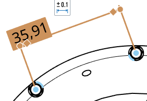
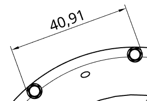
为了明确彼此非常接近的尺寸,您可以使用转折尺寸界线。要向界线添加转折,请右键单击界线以打开环境菜单,然后单击“添加转折”:
默认情况下,转折将出现在界线的中点。将鼠标悬停在尺寸标注线上以亮显捕捉点,然后单击并拖动转折尺寸界线上的捕捉点以根据您的喜好对其进行定位:
您可以(在使用“显示隐藏线”命令之后)标注隐藏线的尺寸。
编辑尺寸的值会使其转换为替代尺寸。请参见尺寸故障排除。
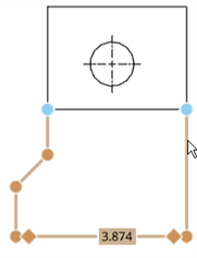
创建尺寸后,将光标悬停在其上,可以看到尺寸中涉及的图元。将光标悬停在图元上时,图元会变成蓝色。
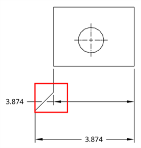
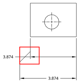
如有必要,您可以编辑现有尺寸的夹点。单击任何夹点并将其拖至另一条边、点、弧、圆或圆心。其他夹点上仍保持关联。例如,在下面的插图中,将尺寸的右侧夹点从点拖至边。
您只需单击并拖动即可拖动尺寸文本。文本上无需有夹点。
选定边后,再次单击(即使是在标注尺寸时)可取消选择它并选择其他边。
您可以更改相交的尺寸线的显示方式,即在相交的位置显示为断开,或在相交的位置显示为不断开。
右击尺寸,然后从环境菜单中选择打断尺寸或取消打断尺寸。只能打断其中一条相交线。
打断的尺寸
不间断的尺寸
您可以通过尺寸调色板来自定义选定尺寸(驱动尺寸与从动尺寸)的外观。选择某个尺寸即可显示尺寸调色板图标。
- 在未选择工具的情况下,选择尺寸。
- 此时将显示尺寸调色板图标
 。
。 - 将鼠标悬停在该图标上可打开调色板。(您也可以双击该尺寸来打开调色板)。
- Set the following options in the palette. Some options may not appear in the palette, depending on the dimension type and other selected options.
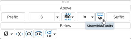
- Above text - Enter the text or symbol to appear above the dimension value.
- Prefix text - Enter the text to appear as a prefix to the dimension value.
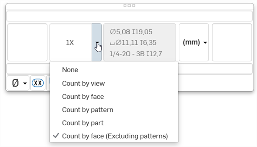
- Count type - Use the dropdown to select a count type for the dimension.
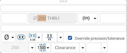
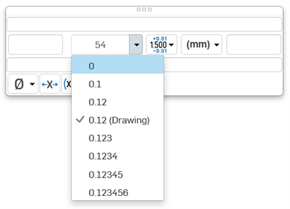
- Precision - Select the depth of unit precision (zero to 8 decimal places).
Precision defined on a drawing dimension may be linked to the Properties panel through this Dimension palette by selecting the tolerance with “(Drawing)” beside it. Whenever the Properties panel tolerance precisions are updated, any dimension with the “(Drawing)” tolerance selected will also be updated. You can choose to link these properties (and unlink them) on a dimension-by-dimension basis.
- Dimension units - Select the units of your choice. The currently selected unit is displayed in the dropdown label:
Choose from: Millimeters, Millimeters (Drawing), Centimeters, Meters, Inches, Inches fractional, Feet and inches, Feet, or Yards. This selection overrides the units for that dimension. If you later change the drawing units, the units for the dimension are not overridden. You can change the units back to (Drawing) if you want to inherit the drawing properties again.
When you choose units, you set two properties in the drawing or on a dimension - the Units property and the Fractional display property.
- Drawing units are managed separately from Workspace units for Part Studios and assemblies
- Feet and Inches is only available in drawings; it is not available for workspace units.
- Toggle the Show/Hide units button as to display or hide the dimension units.
 .
.
- Suffix text - Enter the text to appear as a suffix to the dimension value.
- Below text - Enter the text or symbol to appear below the dimension value.
- Symbol dropdown - Select a symbol to insert from the dropdown:
Symbol Name Shortcut ° Degree %%d ⌀ Diameter %%c ℄ Centerline ⌵ Countersink ↧ Depth ⌴ Counterbore □ Square ⌒ Arc length ± Plus/Minus %%p Ⓤ Unequally disposed profile Ⓘ Independency 
Continuous feature 
Spot face ▷ Translation - Inspection dimension - Toggle to add or remove an oval frame around the dimension to indicate this is an inspection dimension.
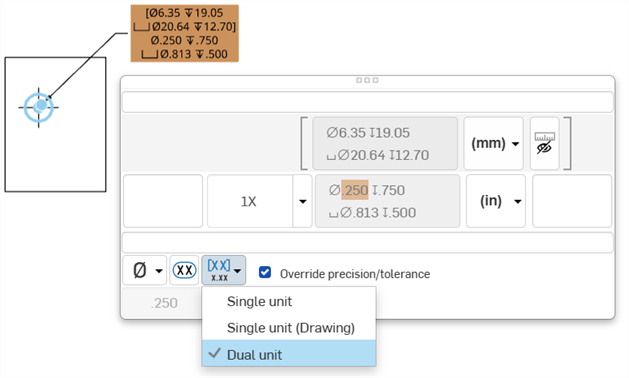
- Dual dimension - Toggle to specify whether to have a single unit dimension, single unit as specified for the drawing properties, or a dual unit dimension:
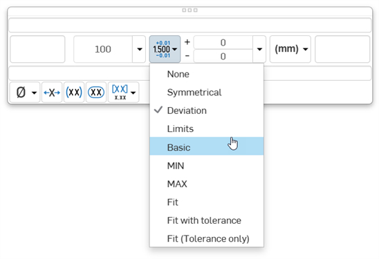
- Tolerance - Select None, Symmetrical, Deviation, Limits, Basic, MIN, MAX, Fit, Fit with tolerance, or Fit (Tolerance only).
- Set the upper and lower tolerance (available for Symmetrical, Deviation, or Limits)
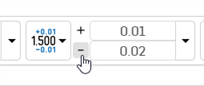
Optionally, to set a Deviation or Limits tolerance to plus/plus (+/+) or minus/minus (-/-), click the plus (+) or minus (-) button, as required:
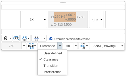
- Set the Fit type, Shaft class, Hole class, and Fit standard (available for Fit, Fit with tolerance, or Fit (Tolerance only))
- Set the precision depth of the Fit tolerance units, from 0 to 8 decimal places (available for Fit with tolerance or Fit (Tolerance only))
- Set the upper and lower tolerance (available for Symmetrical, Deviation, or Limits)
- Reset text position - Toggle to reset the text to the previous location.
- Parentheses - Toggle to add or remove parenthesis around the dimension field.
- Toggle hole class visibility - (Available for Fit and Fit with tolerance options) Use this to show or hide the hole class in the dimension. When shown, select one of the following options:
- Stacked without line
- Stacked diagonally
- Stacked with line
- Toggle Radius/Diameter dimension - Use this to change a radial dimension to diameter or vice versa.
您也可以复制/粘贴到所有文本框,在尺寸和注释中也是如此。
Placing dimension text
- 选择两个图元后,会在预览模式下绘制尺寸,以便最终放置:
- 在预览过程中四处拖动文本可以将文本移至延长线以外,也可以在水平、竖直和对齐测量模式之间切换:
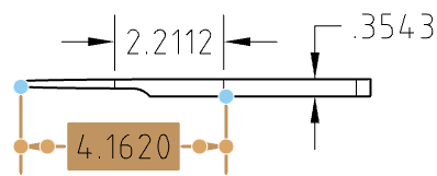
- 在工程图中从两个选定捕捉点向上或向下拖动文本可创建水平尺寸线:
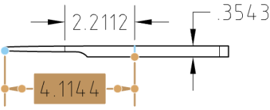
- 将文本从两个选定捕捉点向工程图的一边拖动可创建竖直尺寸线:
- 在垂直于经过两个选定捕捉点的直线的方向上拖动文本可创建平行于这两个选定捕捉点的尺寸线:
将光标悬停在标记上方可唤醒对齐关系。只有在预览模式下会这样。将光标划过其他工程图图元也可唤醒对齐关系,就像其他视图的图元一样。
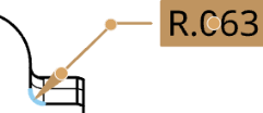
选择尺寸工具后,您可以将光标移至表示环形边的边上方以“唤醒”中心标记。此标记一旦可见,将一直保持可见状态。
将光标移至边上方时,会出现橙色的环形捕捉点与竖直中心标记:
悬停光标后,橙色的捕捉点会消失,但是标记仍可见:
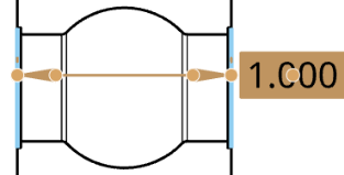
改变尺寸箭头的位置。用于显示箭头或记号的任何尺寸。
当您选择尺寸时,尺寸箭头或记号旁边会显示一个节点。单击节点可翻转尺寸的箭头。
要翻转尺寸箭头:
- 在图形区域中,选择要更改的尺寸。
- 将值拖动到新位置(箭头会相应地变化)。
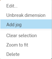
使用鼠标右键单击可在任何尺寸上打开环境菜单,以访问该尺寸的命令选项列表。下面列出了这些命令选项。请注意,此处列出的所有命令并非都适用于每种类型的尺寸。
-
编辑 - 打开尺寸调色板以编辑尺寸。
-
粘贴 - 将尺寸与视图一起粘贴到当前位置。
-
清除选定内容 - 取消选择选定的尺寸。
-
缩放到合适大小 - 将整个工程图缩放到视图中。
-
删除 - 删除选定的尺寸。
您可能会遇到的一些问题包括:
- 悬空尺寸 - 断开关联的尺寸以红色显示。拖动尺寸捕捉点可重新关联到几何图元。请参见悬浮图元获取更多信息。
- 替代尺寸 - 尺寸的文本值转换为非关联的附注。替代尺寸的文本始终带有下划线。编辑尺寸的尺寸值会使其转换为替代尺寸,这样一来:
- 当一个维度被覆盖时,您仍然可以在尺寸调色板中编辑其他字段。
- 您可以将替代尺寸还原为关联的尺寸,方法是删除尺寸值输入框中的字符并退出面板。
- 工程图中带有下划线的尺寸值指示值不按比例变化。