![]()
기준을 사용하여 연관된 기준 기호를 생성하고, 선형 또는 둥근 모서리로 나타나는 면의 도면 뷰에 배치하여 해당 파트에서 기준면을 식별할 수 있습니다.
데이텀과 기하 공차는 도면 내에서 제조 변동을 전달하는 데 없어서는 안 될 부분입니다.
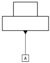
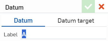
도면에 기준을 추가합니다.데이텀 탭에 있으면 도면 뷰 모서리를 따라 빠르게 데이텀을 배치할 수 있습니다. 레이블 필드는 자동으로 문자로 채워지지만 사용자 지정할 수 있습니다. 뷰 모서리를 클릭하여 지시선에 기준 기호를 부착합니다. 다시 클릭하여 배치합니다. 이 도구는 추가 기호를 계속 배치할 수 있도록 활성 상태로 유지됩니다.
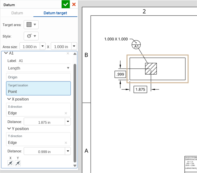
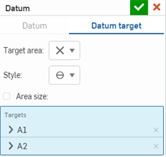
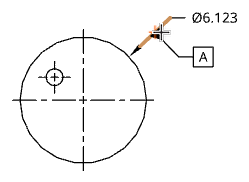
기준 대상 탭을 클릭하여 다른 기준을 적용할 특정 영역을 정의합니다. 대상 영역 드롭다운에서 모양을 선택합니다. 스타일 드롭다운에서 콜아웃을 선택합니다. 영역 크기를 선택하여 대상 모양을 지정합니다. 지름은 X, 점 또는 원의 크기를 정의하고 직사각형의 크기는 측면 길이로 정의됩니다. 드롭다운에서 정밀도를 선택합니다. 지름 값을 입력합니다. 뷰 위치를 클릭하여 기호를 부착합니다. 다시 클릭하여 배치합니다.
대화상자를 수락하거나 대상을 사용하여 차원을 추가하도록 선택합니다. X축과 Y축이 교차하는 꼭지점이 있는 경우 원점 대상 위치를 사용하거나 뷰에서 모서리를 선택하여 X 및 Y 방향을 정의합니다. X 및 Y 반대 방향 화살표를 클릭하여 치수 배치를 반전시킵니다. 기준을 수락합니다.
밑면의 그립 점을 선택하거나 끝을 드래그하여 위치를 조정합니다. 마우스 오른쪽 버튼 클릭 컨텍스트 메뉴에서 편집하거나 마우스 왼쪽 버튼을 두 번 클릭합니다.
기하 공차를 추가합니다.공차 기호를 선택하고 공차를 입력한 다음 필요한 데이텀을 입력합니다. 지시선을 삽입하고 기호를 추가하고 최대 재료 조건과 같은 기하 공차 수정자를 추가합니다. 자유 상태, 탄젠트 면 또는 투영 공차 영역의 조합을 선택합니다.
프레임 추가 아이콘을 클릭하여 프레임을 추가합니다. 연속된 프레임은 컴포지트의 심볼 드롭다운에 새로운 옵션을 제공합니다. 이렇게 하면 심볼이 두 프레임 모두에 걸쳐 있습니다. 마지막 프레임 제거 아이콘을 클릭하여 추가 프레임을 제거합니다.
시트의 아무 곳이나 클릭하거나 치수를 클릭하여 기하 공차를 배치합니다.계속해서 추가 기하 공차를 배치하거나 대화상자를 수락하십시오. 치수에 배치하면 해당 치수에 스냅되고 이동할 때 그 뒤를 따릅니다. 기하 공차를 치수 밖으로 드래그하여 스냅을 해제합니다. 치수로 드래그하여 스냅합니다.
마우스 오른쪽 버튼을 클릭하면 나타나는 컨텍스트 메뉴에서 기하 공차를 편집하거나 마우스 왼쪽 버튼을 두 번 클릭하여 편집 대화상자를 엽니다.
-
 을 클릭하십시오.
 - 대화상자에 필요한 라벨을 입력합니다.
- 클릭해서 파트 보기의 모서리를 선택하고 모서리에서부터 멀리 드래그하여 기준선을 설정합니다.
- 클릭하여 기준 기호를 설정합니다.
마우스를 이동하는 동안 커서가 다른 요소 근처를 통과할 때 빨간색의 얇은 파선이 나타납니다. 이들 선은 치수를 정렬할 수 있는 추론 선에 해당합니다. 선이 나타난 것을 확인했을 때 클릭하면 치수가 해당 선에 맞춰집니다.
-
을 클릭하십시오.
- 기준 대상을 클릭합니다.
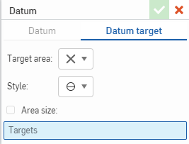
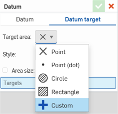
- 대상 면적 드롭다운에서 대상의 모양을 선택합니다.
점(X): 도면 뷰에서 점을 선택합니다.
점(도트): 도면 뷰에서 점을 선택합니다.
- 원: 도면 뷰에서 원형 영역을 정의합니다.
- 직사각형: 도면 뷰에서 직사각형 영역을 정의합니다.
사용자 지정: 도면 뷰에서 닫힌 영역을 지정합니다.
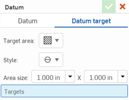
- 드롭다운에서 대상 설명선의 스타일을 선택합니다.
- 대상의 영역 크기를 지정합니다.
(선택 사항)점(X): 면적 크기 상자를 선택하고 지름을 지정합니다. 드롭다운에서 정밀도를 선택합니다
.(선택 사항)점(닷): 면적 크기 상자를 선택하고 지름을 지정합니다. 드롭다운에서 정밀도를 선택합니다.
- 원: 지름을 지정합니다.드롭다운에서 정밀도를 선택합니다.
- 직사각형: 측면 길이를 지정합니다.드롭다운에서 정밀도를 선택합니다.
- 사용자 지정: 사용자 지정 선택 항목에 대한 영역을 수정할 수 없습니다.
- 클릭해서 도면에 대상을 배치합니다.
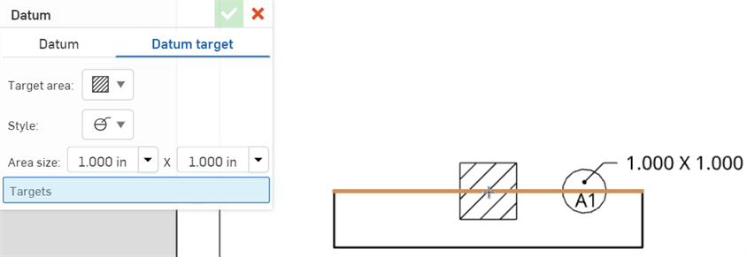
- 다시 클릭하여 대상 설명선을 배치합니다.
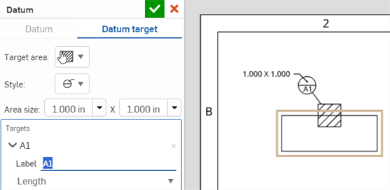
- 필요한 경우 대상 레이블을 변경합니다. 데이텀 대상 대화상자에 대상을 추가하면 레이블 숫자 (A2, A3, A4 등) 가 증가합니다. 새 대상을 추가하면 레이블 문자 (B1, C1, D1 등) 가 증가합니다.
- 다음으로 대상의 원점을 선택합니다. 표적의 정확한 위치는 이 원점을 기준으로 결정됩니다다음으로, 대상의 원점을 선택합니다. 대상의 정확한 위치는 이 원점을 기준으로 결정됩니다. 원점으로부터의 거리 또는 각도로 위치를 지정할 수 있습니다. (사용자 지정 대상 모양에서는 원점을 설정할 수 없습니다.)
- 거리별로 대상 위치를 정의하려면:
- 드롭다운에서 길이를 선택합니다.
- 클릭하여 원점을 배치합니다.
- 원점에서 대상의 X 위치와 Y 위치까지의 거리를 지정합니다.
- 선택적으로 거리 드롭다운을 클릭하여 정밀도를 설정할 수 있습니다.
- X 및 Y 화살표 버튼을 사용하여 원점과 관련해서 대상의 방향을 변경합니다.
- 대상을 각도로 정의하려면:
- 드롭다운에서 각도를 선택합니다.
- 원점을 원이나 호의 중심에 배치하려면 클릭합니다.
- 원점에서 대상의 지름 거리를 지정합니다. 타겟은 원점으로부터 이 거리의 절반(즉, 반경 거리)에 위치하게 됩니다.
- 다음으로 대상의 각도를 지정합니다. 타겟은 수평에서 이 각도로 배치됩니다.
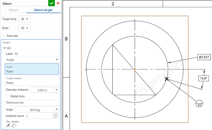
- 필요에 따라 지름 거리 및 각도 드롭다운을 클릭하여 정밀도를 설정할 수 있습니다.
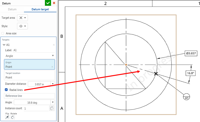
- 원점에서 대상까지의 선을 표시하려면 방사형 선 옵션을 클릭합니다.
- 수평 참조와 다른 참조를 지정하려면 참조선 필드를 클릭하고 모서리를 선택합니다. 타겟은 이 라인으로부터 일정 각도로 배치됩니다.
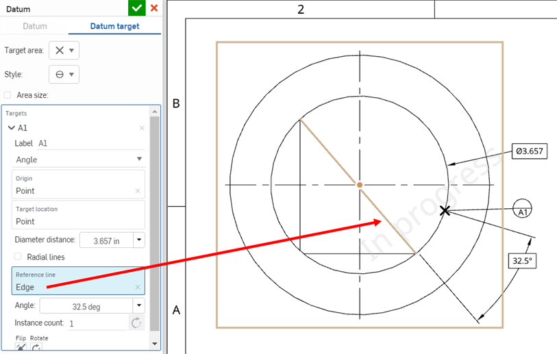
- 필요에 따라 뒤집기 및 회전 버튼을 사용하여 원점을 기준으로 대상의 방향을 변경합니다.
- 부품(Instance) 옵션을 사용하여 대상 데이텀 부품을 추가합니다. 모든 부품은 360도 호를 따라 균일한 간격으로 배치됩니다. 반대 방향 버튼을 클릭하여 부품을 시계 방향이 아닌 시계 반대 방향으로 정렬합니다.
- 거리별로 대상 위치를 정의하려면:
- 데이텀 대상 대화상자의 대상 필드를 클릭하여 대상을 더 추가합니다(대상을 추가하려면 공간 클릭 툴팁이 표시됨). 대화상자에 추가된 모든 대상은 동일한 앞 문자(예: A1, A2, A3 등)로 시작됩니다.
- 체크마크를 클릭하여 기준 대화상자를 닫습니다.
-
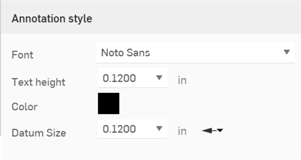
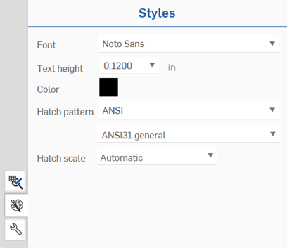
스타일링하려는 기준을 클릭한 다음, 페이지의 오른쪽에서 스타일 패널 아이콘을 클릭합니다.
-
글꼴, 문자 높이, 색상, 해치 패턴 및 해치 배율을 편집합니다.
![]()
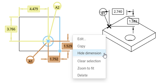
- 숨기려는 차원을 마우스 오른쪽 단추로 클릭한 다음 차원 숨기기를 클릭합니다.
- 숨기려는 각 치수에 대해 반복합니다.
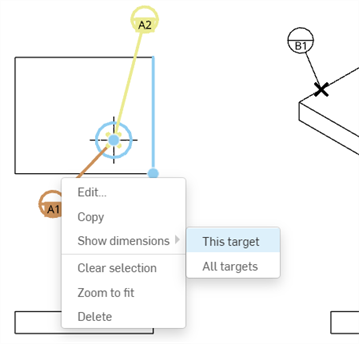
- 숨겨진 차원을 표시하려면 대상 레이블을 마우스 오른쪽 단추로 클릭한 다음 차원 표시를 선택합니다.
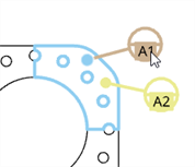
- 해당 대상(아래 예의 A1)에 대한 차원만 표시하려면 이 대상을 클릭합니다.
- 해당 레이블(아래 예의 A1 및 A2)과 연결된 모든 대상의 모든 차원을 표시하려면 모든 대상을 클릭합니다.
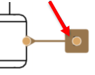
- 배치 후 기준을 다른 위치로 드래그할 수 있습니다. 기준을 클릭하여 선택한 후 드래그하십시오.
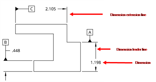
- 기준을 도면의 해당 배치 점에 더 가까이 또는 더 멀리 드래그할 수 있으며, 그러면 연장선이 적절하게 조정됩니다.
- 기준을 설명선과 그룹으로 묶을 수 있습니다. 자세한 내용은 설명선(풍선)을 참조하십시오.
-
치수 지시선의 어느 곳에나 기준을 배치할 수 있습니다.
-
기준은 선형 치수 선 확장에도 배치될 수 있습니다.
-
기준을 선 확장에 배치하고 선 확장 너머로 끌 수 있습니다.
-
기준이 치수 화살촉이나 선을 가리는 경우 가려진 엔터티는 숨겨집니다.
-
- 라벨을 변경하려면 기준을 클릭해서 선택한 다음, 강조 표시된 사각형 안을 두 번 클릭합니다.
기준 대화상자가 열리고 라벨을 변경할 수 있습니다. 또한 속성 패널, 주석 탭, 화살표 머리 설정을 통해 모든 화살표 머리에 대한 속성 설정에서 삼각형을 변경할 수 있습니다.
-
시리즈에서 데이텀 대상을 선택하면 대상 및 관련 면이 파란색으로 강조표시됩니다.시리즈의 다른 모든 데이텀은 노란색으로 보조 강조 표시됩니다.
-
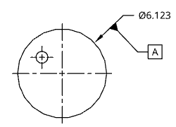
홀 설명선과 반경 및 지름 치수에 기준 기호를 첨부할 수 있습니다. 그러나 단축 치수(예: 디테일 뷰의 치수)로 변환할 수 있는 반경 또는 지름 치수에는 기준 기호를 첨부할 수 없습니다.