 단면도
단면도
![]()
![]()
![]()
이용 가능 플랫폼: Part Studio, 어셈블리
단면도에서는 단면 생성에 사용할 면, 메이트 커넥터, 원통형 면, 원뿔형 면 또는 평면을 하나 또는 여러 개 선택할 수 있습니다. 또한 기본 면을 선택하는 데에도 사용할 수 있습니다. 단면도는 카메라 및 음영처리 옵션 메뉴를 통해 활성화하거나 컨텍스트 메뉴에서 단면도를 선택하여 켤 수 있습니다.
일단 매니퓰레이터가 가시화되면, 볼(중심에서 열린 원)을 통해 이동하여 파트, 면 또는 어셈블리의 구속 제한 점에 스냅시킬 수 있습니다. Part Studio와 어셈블리 양쪽 모두에서 단면이 잘린 아이템을 볼 수 있습니다.
- 파트 또는 면에서 하나의 면, 메이트 커넥터, 원통형 면, 원추형 면 또는 평면을 선택합니다.
- 카메라 및 음영처리 옵션 메뉴
 를 확장하고 단면도를 선택합니다(아래 그림 참조). 또는 Part Studio의 파트나 어셈블리 탭의 어셈블리를 마우스 오른쪽 버튼으로 클릭하고 컨텍스트 메뉴에서 단면도를 선택합니다.
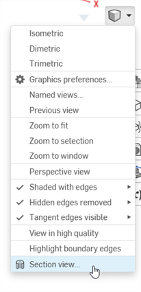
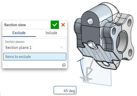
- 위 1단계에서 선택한 점(원통형 면, 원뿔면, 평면, 면 또는 메이트 커넥터)에서 파트/면이 절단됩니다. 마지막으로 선택한 위치에 매니퓰레이터가 나타나고 선택 항목이 나열된 대화상자가 열립니다.
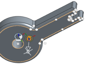
- 매니퓰레이터의 열린 원(볼)을 클릭하고 드래그하여 위치시킵니다. 원통의 중심을 포함하여 파트 또는 어셈블리의 구속 제한 점에 스냅할 수 있습니다(아래의 흰색 표시는 구속 제한 점을 나타냄).
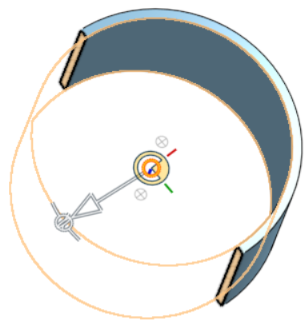
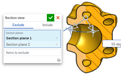
- 매니퓰레이터를 사용하여 단면의 깊이 및/또는 각도를 변경합니다.
- 화살표를 사용하여 한 방향이나 다른 방향으로 드래그하여 깊이를 변경할 수 있습니다. 보기의 방향을 뒤집으려면 매니퓰레이터를 클릭하십시오.
- 각도 표시기를 사용하여 각도에서 드래그합니다.
- 그래픽 영역의 숫자 입력란을 사용하여 뷰의 깊이 또는 각도를 입력합니다.

- 대화상자가 열려 있는 동안 다른 단면을 선택하려면, 새로운 단면에 대해 원하는 위치를 클릭하기만 하면 새로운 매니퓰레이터와 단면이 나타납니다.
단면도 면에 대한 수직 단면을 보려면, 단축키 N을 사용하거나 마우스 오른쪽 버튼을 클릭하고 컨텍스트 메뉴에서 수직으로 보기를 선택합니다.
- 하나 이상의 파트/면을 단면에서 제외하려면 필드를 제외할 항목을 활성화한 다음, 그래픽 영역에서 항목을 선택합니다.
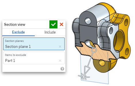
-
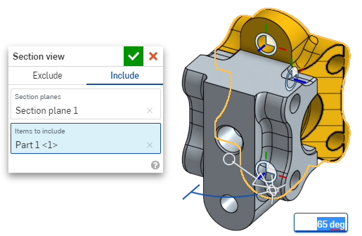
하나 이상의 파트/면을 단면에 포함시키려면 포함 탭을 선택한 다음, 그래픽 영역에 포함시킬 항목을 선택합니다.
단면도 상태에서 모델을 이동하려면 대화상자를 닫고 원하는 대로 모델을 조작합니다.
- 대화상자에서 기본 면 선택 아이콘
 을 클릭하여 그래픽 영역에서 기본 면 옵션을 엽니다.
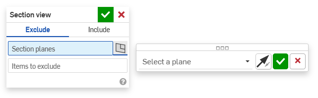
-
드롭다운 메뉴에서 기본 면을 선택하면 단면도 대화상자가 그에 따라 업데이트됩니다.
필요에 따라 '면 뒤집기' 아이콘을 클릭하여 앞/뒤, 위/아래 또는 오른쪽/왼쪽 보기 사이를 쉽게 전환할 수 있습니다.
-
면 선택 옵션 대화상자에서 녹색 확인란을 클릭하면 기본 면 옵션이 저장되고 닫히지만 단면도 대화상자는 열린 상태로 유지됩니다. 또는 단면도 대화상자에서 녹색 확인란을 클릭하면 두 대화상자 모두 저장된 후 닫힙니다.
-
완료 후 카메라 및 음영처리 옵션 메뉴
또는 컨텍스트 메뉴에서 단면도 끄기를 선택합니다.
선택하기 전에 단면 뷰를 켤 수도 있습니다.
교차하는 파트가 있을 경우, 해당 파트가 빨간색으로 표시됩니다.
단면도가 꺼지지 않고 대화상자가 닫혔을 때 단면을 두 번 클릭해서 대화상자를 다시 엽니다. 또는 카메라 및 음영처리 옵션 메뉴 ![]() 를 클릭하거나 파트 또는 어셈블리를 마우스 오른쪽 버튼으로 클릭하여 컨텍스트 메뉴에 액세스하고 단면도 편집을 선택합니다.
를 클릭하거나 파트 또는 어셈블리를 마우스 오른쪽 버튼으로 클릭하여 컨텍스트 메뉴에 액세스하고 단면도 편집을 선택합니다.
단면도를 사용한 다음, 해당 뷰를 명명된 뷰로 저장할 수 있습니다.
단면도에서 면, 모서리, 꼭지점에 대해 측정 도구를 사용할 수도 있습니다. 자세한 내용은 측정 도구를 참조하십시오.