곡선/면 분석
![]()
이용 가능한 플랫폼: 스케치, Part Studio, 어셈블리
단축키: shift+c
곡선/면 분석은 Part Studio에서 스케치 또는 파트의 곡률을 다양한 방법으로 시각화하고 분석합니다. 단축키(Shift+c) 또는 스케치, 파트, 표면의 컨텍스트 메뉴 또는 인터페이스 오른쪽 하단의 분석 도구 표시 메뉴를 통해 곡선/면 분석 대화상자에 접근할 수 있습니다.
스케치 모드에 있거나 스케치를 편집 중일 때 Shift+c 단축키를 사용해 모든 스케치 곡선을 자동으로 선택하고 곡률/면 분석 대화상자를 열 수 있습니다. Shift+c는 토클로 작동하며, 선택 항목이 지속되는 동안 대화상자를 열고 닫습니다.
곡선/면 분석 툴은 스케치를 종료한 후에도 계속 열려 있지만, 선택 필드가 활성 상태가 아닙니다. 도구가 열려 있는 동안 선택 항목을 더 추가하거나 제거할 수 있습니다. 선택 항목의 변경 내용은 다음 번 해당 도구를 호출할 때까지 지속됩니다. 도구를 열기 전에 미리 선택한 경우, 방금 선택한 항목으로 도구가 열리고 이전에 선택한 모든 항목을 선택이 취소됩니다.
곡선과 면을 검사하려면:
- 인터페이스의 오른쪽 하단 코너에서 분석 도구 표시(
 )를 클릭합니다.
 - 곡선/곡면 분석을 선택하여 대화상자를 엽니다. 그래픽 영역에서 스케치나 파트를 마우스 오른쪽 버튼으로 클릭하고 컨텍스트 메뉴에서 선택하여 이 대화상자에 액세스할 수도 있습니다.
-
분석할 모서리와 면을 선택합니다. 또는 대화상자에 접근하기 전에 미리 선택할 수도 있습니다.
- Select from the following options:
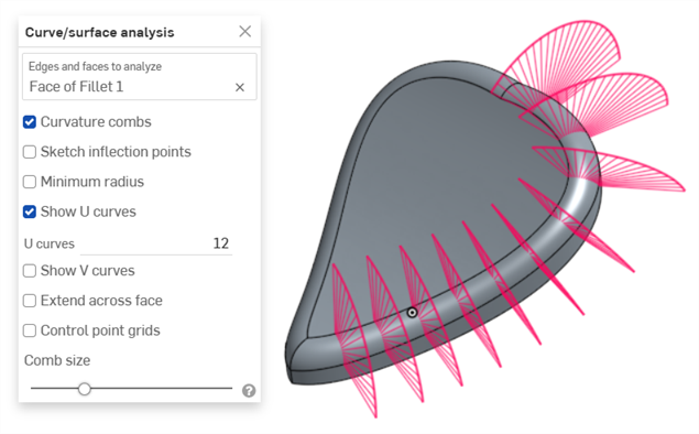
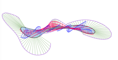
Curvature combs - Displays the combs of the selected edge(s) and/or face(s) along the U and V directions. Curvature combs are evaluated at evenly spaced isolines, not necessarily at the control points, and are used for evaluating the resultant shape of a curve/surface up to Flow (G3) continuity.
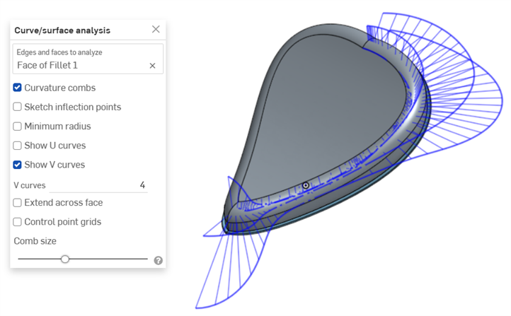
Curvature combs on the V direction on a face
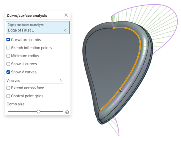
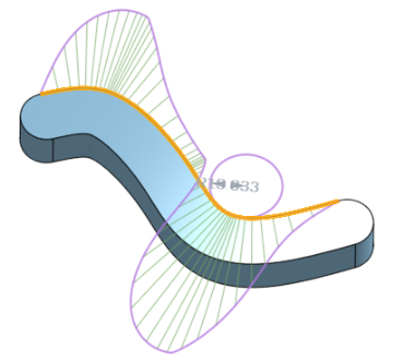
Curvature combs on an edge. Combs are shown in green, bounded in magenta.
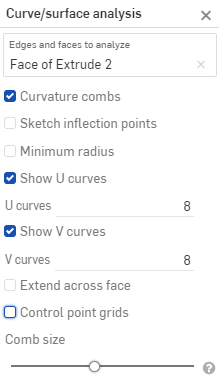
Show U curves - Displays curvature combs along the U direction. U curves are displayed in red:
Show V curves - Displays curvature combs along the V direction. V curves are displayed in blue:
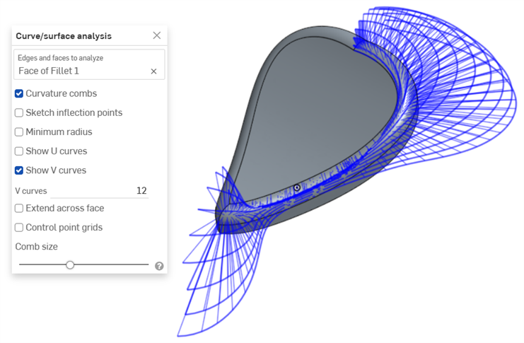
Increase or decrease the number of curves using the numeric U curves and V curves fields, from 2 to 64. The default is 8 for each.
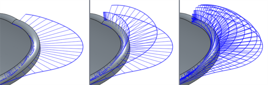
V curves set at 2 (left), 4 (middle), and 8 (right)
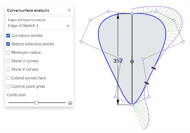
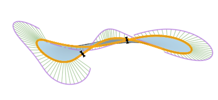
Sketch inflection points (sketch only) - Displays the inflection points along a sketch edge. They appear as black 'bow ties':
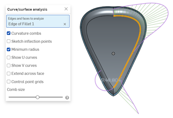
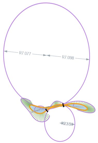
Minimum radius (edges only) - Shows the minimum radius along an edge, either a sketch or part edge:
Extend across face - Extends the curvature combs along adjacent faces:
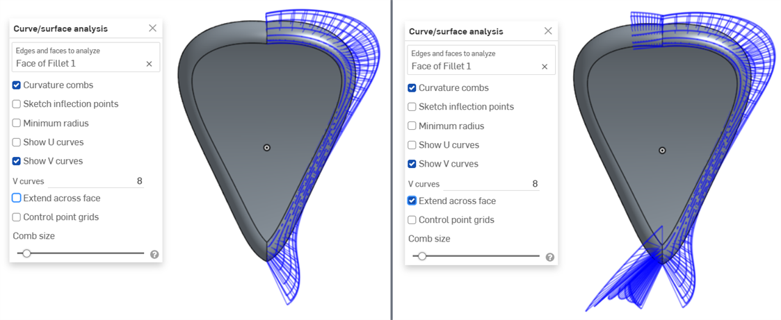
Curvature combs not extended across faces (left) and extended across faces (right)
Control point grids - Displays the control points grid for the selected edge, either a sketch or part edge. This is the location of the control points on the underlying bSpline curves that define the surface (or curve). The number and distribution of the control points provides important information about the underlying math defining the shape.
Dense clusters of control points indicate potential problem areas, and can be deleterious to the surface quality. In short, control point grid is used to understand the underlying mathematical definition of the surface/curve,
Control point grids are shown in magenta:
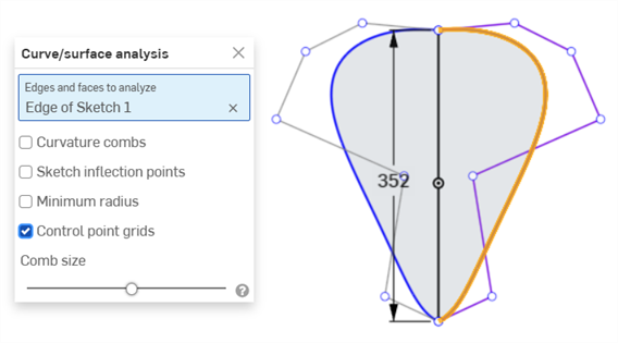
Control point grids displayed in magenta
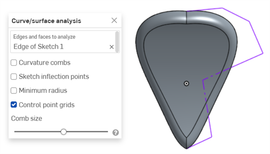
Control point grids displayed with the sketch closed and the part displayed
Knot points - Displays the knot points on the selected curve or surface. (Not available for non-spline entities such as cylindrical faces, intersection curves, offset curves, etc.)
Details - Displays details (such as degree, spans, and number of control points) upon hovering over the selected curve or surface. (Not available for non-spline entities such as cylindrical faces, intersection curves, offset curves, etc.)
Comb size - Use the slider at the bottom of the dialog to adjust the magnitude of the combs.
-
필요하면 곡선을 클릭해서 드래그하여 곡률을 조정하십시오. 드래그하는 동안 조합이 동적으로 업데이트됩니다.
-
완료되면
 을(를) 클릭하여 곡선/면 분석 대화상자를 닫습니다.
또는 처리 중(예: 돌출 중)인 피처의 곡률 콤보를 볼 수도 있습니다.
- 피처 대화상자가 열려 있는 상태에서 그래픽 영역을 마우스 오른쪽 버튼으로 클릭하고 곡선/면 분석을 선택하여 곡선/면 분석 대화상자를 엽니다.
- 피처의 곡선 선택:
- 새로운 피처를 생성하는 데 사용되는 선택한 모서리에 대한 곡률을 표시하거나(미리 확인한 모서리에 대해 표시의 선택 취소), 미리 확인한 모서리에 대해 표시를 선택해서 생성할 새로운 피처의 모서리에 대한 곡률 콤보를 확인할 수 있습니다.
곡률 표시 대화상자에서 해당 옵션 왼쪽에 있는 확인란을 선택하면 곡률 조합 표시, 변곡점 및 최소 반지름을 표시할 수도 있습니다.
곡률 표시 대화상자에서 미리 확인한 모서리에 대해 표시, 곡률 콤보 표시, 스케치 변곡점 표시, 최소 반경 표시를 선택했을 때 피처의 예.
곡선 및 면 분석에 대한 추가 정보는 면 모델링을 참조하십시오.