 사용
사용
![]()
![]()
![]()
부품이나 스케치의 모서리, 모서리 및 실루엣 모서리를 활성 스케치 평면에 투영 (또는 변환) 합니다.
단축키: u
부품의 모서리, 모서리 및 실루엣 모서리를 투영 또는 변환하거나 활성 스케치 평면에 스케치하려면 새 스케치를 작성하고 사용할 평면을 선택한 다음 스케치 도구 모음에서 사용 (프로젝트/변환) 스케치 도구를 클릭합니다.이제 평면을 기준으로 나타나는 선을 선택할 수 있습니다.작업을 마쳤으면 초록색 체크 표시를 클릭하여 스케치를 적용하면 이제 부품을 기반으로 한 새 스케치가 만들어집니다.
단계
- 스케치 또는 파트를 생성합니다.
- 다른 스케치를 시작합니다.
- 클릭
 그런 다음 첫 번째 스케치나 부품의 모서리, 모서리 또는 실루엣 가장자리를 선택합니다.
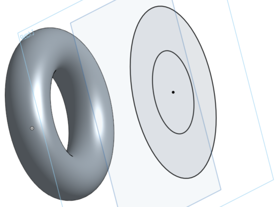
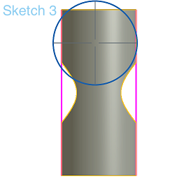
이 예에서는 스케치 면에서 사용(투영)하기 위해 파트의 강조 표시된 모서리가 선택되었으며, 그 결과로 강조 표시된 수평선이 나타납니다.
요소 위로 마우스를 가져가면 투사된 선의 미리보기가 나타납니다.
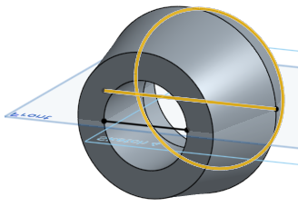
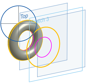
실루엣 모서리 사용
스케치에 수직인 모델을 볼 때 모서리가 아닌 가시적인 경계는 모두 실루엣 모서리입니다. 즉, 표면이 사용자를 향하던 것에서 반대쪽을 향하는 것으로 전환됩니다.
실루엣 엣지는 어떻게 사용되나요?
-
을 클릭합니다.
참고로 실루엣 모서리에는 사전 선택 동작이 없습니다.
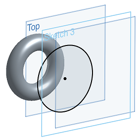
- 실루엣 테두리를 원하는 얼굴 위로 마우스를 가져갑니다.
하이라이트가 보일 것입니다.실제 실루엣 모서리가 스케치 평면을 벗어나면 두 개가 보입니다.하나는 '실제' 실루엣 모서리이고 다른 하나는 스케치 평면의 투영입니다.둘 다 선택할 수 있습니다.
- 마우스를 가져간 다음 하이라이트를 클릭하여 실루엣 가장자리를 투영합니다.(위에서 선택하기 위해 마우스오버한 하이라이트는 노란색 하이라이트로 표시됩니다.)
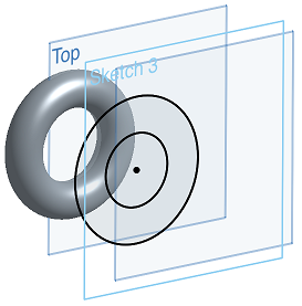
여러 실루엣 모서리를 사용할 수 있는 경우 면을 클릭하여 모든 실루엣 가장자리를 선택하거나 개별 실루엣 모서리 위로 마우스를 가져간 다음 사용하려는 모서리만 클릭하여 선택할 수 있습니다.
이것은 마우스로 가리키는 동안 나타나는 하이라이트입니다.
선택 및 다른 면에 투사 후:
요소 위로 마우스를 가져가면 투사된 선의 미리보기가 나타납니다.
하이라이트를 볼 수 없는 경우, 제한된 상태로 실행 중일 수 있습니다. 아래의 팁을 참조하십시오.
팁
- 기본 형상이 변경되면 사용된 모든 모서리가 업데이트됩니다. 그러나 모델 변경으로 인한 형상 유형의 변경(원에서 선으로 변경 등)에는 제대로 적용되지 않습니다.
- Onshape 사용 중 다음을 포함한 일부 사항은 다른 시스템과 차이가 있을 수 있습니다.
- Onshape는 실루엣 가장자리의 끝을 제한하지 않습니다.끝 부분을 고정하는 방법을 선택할 수 있습니다.
- Onshape는 실루엣 가장자리의 “비트”를 구분하지 않습니다. 예를 들어 구멍이 뚫린 실린더의 예와 같습니다.
- Onshape는 구멍이 뚫린 위의 원통처럼 면을 사용하지 않고 가장자리 또는 실루엣 가장자리를 자동으로 추출하여 모두 함께 재봉합니다.
- Onshape는 추적 가능한 실루엣 가장자리만 사용합니다.이를 통해 실루엣 엣지가 나중에 업데이트될 수 있다는 확신을 가질 수 있습니다.
- 지원되는 실루엣 모서리에는 원통, 원추, 원뿔체, 구, 돌출된 표면 및 실루엣 가장자리가 하나 있는 모든 표면이 포함됩니다.
- 투영 후 자체 교차하는 실루엣 모서리는 사용할 수 없습니다.
Project (or convert) an edge, edges, and silhouette edges of a part or sketch onto the active sketch plane.
Steps
- Create a sketch or part.
- Start another sketch.
- Tap , then select an edge, edges, or silhouette edge from the first sketch or part.
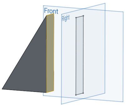
Here, the highlighted face was selected to use (project) onto the Right sketch plane, resulting in the black sketch lines that form a rectangle on the Right sketch plane.
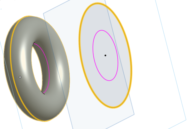
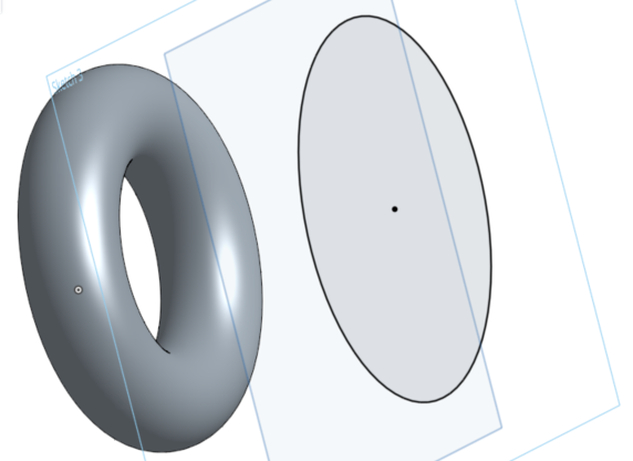
Using silhouette edges
When viewing a model normal to a sketch any visible boundary that isn't an edge is a silhouette edge; where the surface transitions from facing you to facing away from you.
How does using a silhouette edge work?
- Tap .
- Use the Precision selector to hover over the face for which you want a silhouette edge. See Selection for more info.
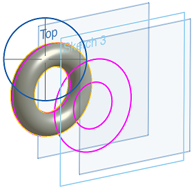
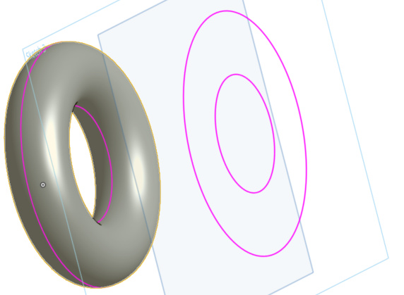
The projection of the silhouette edge appears in pink on the active sketch plane.
- Hover over (line the cross-hairs up with) a specific pink silhouette edge section and it turns yellow to indicate that it is selected. Release to select it and that silhouette edge is now projected onto your current sketch plane.
- If you do not specify a selection by hovering over a pink silhouette edge to turn it yellow, then releasing to select will project all of the silhouette edge options.
This may be used as a more efficient way of projecting an entire silhouette edge at once.
There is NO pre-select behavior for silhouette edges.
Tips
- All used edges update when the underlying geometry changes. However, this doesn't react well to changes of geometry type (circle to line, etc.) causes by model changes.
- Some things about Onshape Use may be different from other systems, including:
- Onshape does not constrain the ends of the silhouette edge. You are able to choose how to fix the ends.
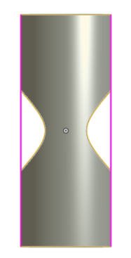
- Onshape does not distinguish between "bits" of silhouette edges, like in this example of a cylinder with a hole through it:
- Onshape does not use a face, like the cylinder above with a hole through it, and automatically extract either edges or silhouette edges and sew them all together.
- Onshape only uses silhouette edges that are trackable. This enables that the silhouette edge can still be updated later.
- Supported silhouette edges include cylinders, cones, tori, spheres, extruded surfaces, and any surface with one silhouette edge.
- Silhouette edges that are self-intersecting after projection are not usable.
Project (or convert) an edge, edges, and silhouette edges of a part or sketch onto the active sketch plane.
Steps
- Create a sketch or part.
- Start another sketch.
- Tap , then select an edge, edges, or silhouette edge from the first sketch or part.
Here, the highlighted face was selected to use (project) onto the Right sketch plane, resulting in the black sketch lines that form a rectangle on the Right sketch plane.
Using silhouette edges
When viewing a model normal to a sketch any visible boundary that isn't an edge is a silhouette edge; where the surface transitions from facing you to facing away from you.
How does using a silhouette edge work?
- Tap .
- Use the Precision selector to hover over the face for which you want a silhouette edge. See Selection for more info.
The projection of the silhouette edge appears in pink on the active sketch plane.
- Hover over (line the cross-hairs up with) a specific pink silhouette edge section and it turns yellow to indicate that it is selected. Release to select it and that silhouette edge is now projected onto your current sketch plane.
- If you do not specify a selection by hovering over a pink silhouette edge to turn it yellow, then releasing to select will project all of the silhouette edge options.
Use this as a more efficient way of projecting an entire silhouette edge at once.
There is NO pre-select behavior for silhouette edges.
Tips
- All used edges update when the underlying geometry changes. However, this doesn't react well to changes of geometry type (circle to line, etc.) causes by model changes.
- Some things about Onshape Use may be different from other systems, including:
- Onshape does not constrain the ends of the silhouette edge. You are able to choose how to fix the ends.
- Onshape does not distinguish between "bits" of silhouette edges, like in this example of a cylinder with a hole through it:
- Onshape does not use a face, like the cylinder above with a hole through it, and automatically extract either edges or silhouette edges and sew them all together.
- Onshape only uses silhouette edges that are trackable. This means that the silhouette edge may still be updated later.
- Supported silhouette edges include cylinders, cones, tori, spheres, extruded surfaces, and any surface with one silhouette edge.
- Silhouette edges that are self-intersecting after projection are not usable.