 금속 판재 로프트
![]()
![]()
![]()
iOS 및 Android에서 지원하는 금속 판재 로프트 피처는 데스크톱(브라우저) 플랫폼에서 생성된 로프트를 보고 편집하는 것으로 제한됩니다.
이용 가능 플랫폼: Part Studio
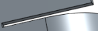
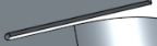
두 프로파일 사이를 연결하는 금속 판재 파트를 생성합니다.
금속 판재 로프트를 만들려면:
- Part Studio에서 금속 판재 로프트 버튼(
 )을 클릭합니다.
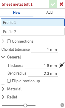
- 새 금속 판재 파트를 만들려면 새로 만들기를 선택하거나 기존 파트에 로프트를 추가하려면 추가를 선택합니다.
- 프로파일 1 필드에 초점을 맞춘 후 시작 프로파일(영역, 면, 모서리 또는 점)을 선택합니다.
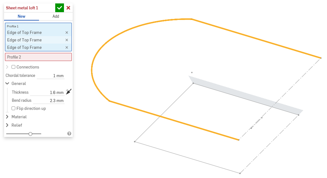
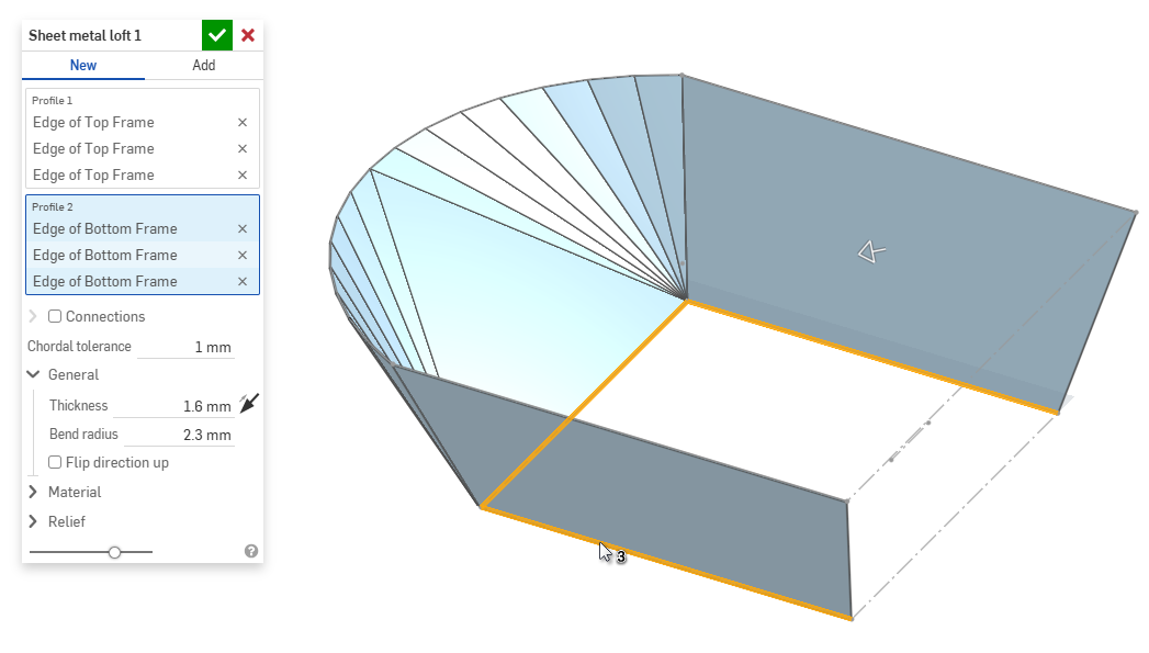
- 프로파일 2 필드에 초점을 맞춘 상태에서 끝 프로파일을 선택합니다. Onshape는 두 프로파일 사이에 금속 판재 모델을 생성합니다.
- 결과 모델의 비틀림을 더 세밀하게 제어하려면 연결 확인란을 클릭합니다. 일치하는 항목이 지정되지 않은 경우 Onshape는 기존 꼭지점/모서리 내의 근접성을 추정합니다.
- 로프트에서 꼭지점이나 모서리를 선택하고 매니퓰레이터를 드래그하여 연결을 조정합니다.
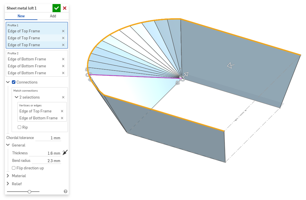
- 연결 부위에서 모델을 별도의 파트로 나누려면 립을 선택합니다.
- 로프트에서 꼭지점이나 모서리를 선택하고 매니퓰레이터를 드래그하여 연결을 조정합니다.
- 현 공차 필드를 사용하여 테셀레이션된 형상이 기본 표면에서 벗어날 수 있는 최대 거리를 설정합니다.
- 새로운 금속 판재 모델을 만들 때 다음 섹션을 확장하여 모델을 더욱 세밀하게 다듬을 수 있습니다.
- 일반:
- 두께 - 금속 판재의 두께입니다. 화살표를 클릭하면 방향이 반전됩니다.
- 벤드 반지름 - 생성된 벤드의 내부 반지름입니다.
- 위로 방향 뒤집기 - 금속 판재 모델과 평면도의 방향을 반전시키려면 이 옵션을 선택합니다. 이는 벤드가 모델을 기준으로 위쪽인지 아래쪽인지 정의할 때 유용합니다.
- 재질(이 섹션의 옵션은 금속 판재 모델 피처에서 제공되는 옵션과 동일합니다):
- 굽힘 계산 - 굽힘 계산 방법을 결정합니다. 옵션은 다음과 같습니다.
- K 계수(기본값) - 중립 축과 재료 두께의 비율을 사용합니다.
- 굽힘 허용량 - 굽힘의 접점 사이의 중립선 호 길이를 사용합니다.
- 굽힘 추정 - 플랜지 길이(모서리부터 꼭지점까지)와 초기 플랫 길이의 합계 차이를 사용합니다.
여기서 선택한 굽힘 계산은 판금 테이블의 열로 사용됩니다. 각 굽힘을 사용자 정의하고 테이블에서 직접 편집할 수 있습니다. 자세한 내용은 금속 판재 테이블 및 평면도를 참조하십시오.
- 기본 굽힘 K 지수 - 굽힘에서 중립축이 놓이는 재료 두께의 비율입니다. (기본값은 0.45입니다.)
- 롤링 K 지수 - 롤링 벽 단면에서 중립축이 놓이는 재료 두께의 비율입니다. (기본값은 0.5입니다.)
- 굽힘 계산 - 굽힘 계산 방법을 결정합니다. 옵션은 다음과 같습니다.
- 릴리프(이 섹션의 옵션은 금속 판재 모델 피처에서 제공되는 옵션과 동일합니다):
- 최소 간격 - 립을 정의하는 금속 판재 가장자리 사이의 최소 간격입니다.
- 코너 릴리프 유형:
- 정사각형 - 확대됨
평면도:
 3D 뷰:
3D 뷰: 
- 직사각형 - 확대됨
플랫 뷰:
 3D 뷰:
3D 뷰: 
- 원형 - 확대됨
평면도:
 3D 뷰:
3D 뷰: 
- 원형 - 확대됨
평면도:
 3D 뷰:
3D 뷰: 
- Closed
플랫 뷰:
 3D 뷰:
3D 뷰: 
- 단순
평면도:
 3D 뷰:
3D 뷰: 
- 정사각형 - 확대됨
- 코너 릴리프 축척 - 코너 입구의 크기(축척된 입구의 경우)는 1.00에서 2.00 사이의 값입니다. 벤드 릴리프 유형 - 벤드 릴리프의 모양:
- 직사각형 - 확대/축소됨
- 장박형 - 확대/축소된
- 전단

- 직사각형 - 확대/축소됨
- 벤드 릴리프 깊이 축척 - 1.00에서 5.00 사이의 값입니다. 값을 입력하면 모든 통합문서의 기본값으로 적용됩니다.
- 값이 1이면 곡면에 완벽하게 밀착되는 타원형 벤드 릴리프가 생성되고, 직사각형 벤드 릴리프는 타원형의 깊이와 일치합니다.
- 1을 초과하는 값은 다음 공식을 통해 깊이를 더합니다.
(depth scale -1) * bendRadius
- 벤드 릴리프 너비 축척 - 0.0625에서 2.00 사이의 값입니다. 값을 입력하면 모든 통합문서의 기본값이 됩니다. 벤드 릴리프 너비는 다음 공식을 통해 계산됩니다.
thickness * width scale.
- 일반:
- 기존 금속 판재 모델에 추가할 때는 병합 범위 필드를 클릭한 다음 추가할 파트를 선택합니다. 병합 범위에는 단일 활성 금속 판재 모델의 바디만 허용됩니다.
금속 판재 모델이 활성화된 경우(생성 또는 편집 중), 추가 도구를 사용할 수 있습니다.
-
 플랜지 - 선택한 각 모서리에 대해 벽을 생성하고 선택한 모서리에 굽힘으로 연결합니다.
 -
 둘러싸기 - 기존의 금속 판재 파트에서 선택한 각 모서리/면에 대해 둘러싸기를 생성합니다.
 -
 탭 - 금속 판재 플랜지에 탭을 추가합니다.
 -
 굽힘 - 추가 굽힘 제어 옵션을 사용하여 참조선을 따라 금속 판재 모델을 굽힙니다.
 -
 양식 - 기존 금속 판재 모델에 양식 피처를 생성합니다. 현재 통합문서, 다른 통합문서 또는 미리 정의된 금속 판재 양식 라이브러리에서 양식을 선택할 수 있습니다.
 -
로프트 - 두 프로파일을 연결하는 금속 판재 모델을 생성합니다.
-
 조인트 만들기 - 두 벽의 교차점을 굽힘(원통형 형상으로 결합된 벽) 또는 립(두 벽 사이의 작은 간격)과 같은 조인트 피처로 변환합니다.
 -
 코너 - 코너 유형과 릴리프 스케일을 수정합니다.
 -
 굽힘 릴리프 - 굽힘 릴리프(굽힘 끝이 자유 모서리와 만나는 작은 컷), 깊이 및 릴리프 너비를 수정합니다.
 -
 조인트 수정 - 굽힘을 립으로 변환하는 등 기존의 조인트에 대한 변경을 수행합니다. 현재 플랫 뷰 테이블을 통해 사용할 수 있습니다.
 -
 코너 분리 - 필렛이나 모따기를 적용하여 기존 금속 판재 파트의 코너를 끊습니다. 코너 모서리 또는 꼭지점을 선택하고 코너 분리 유형과 거리를 지정합니다. 금속 판재 모델의 모든 플랜지와 조인트를 완성한 후에 이 피처를 사용하는 것이 좋습니다.
 -
 금속 판재 테이블 및 플랫 뷰 - 금속 판재 모델 플랫 패턴의 립/굽힘 테이블 및 시각화를 열고 닫습니다. 이 테이블을 사용하여 립을 굽힘으로 변환하거나 반대로 변환할 수 있습니다.
 -
 금속 판재 모델 마감 - 금속 판재 모델을 닫거나 비활성화하고 피처 리스트에 피처를 생성합니다.