![]()
![]()
![]()
モバイルプラットフォームでは、パフォーマンスを維持するために、メッシュのポリラインはブラウザプラットフォームと同じようには表示されません。
メッシュを Onshape ドキュメントにインポートし、そのメッシュに関連するソリッド (解析) ボディをモデリングして、混合モデルを作成します。メッシュ、混合モデル、および解析モデルを使用してアセンブリを作成できます。混合モデルのエクスポートは、Parasolid 形式で最も効果的です。
フィーチャーツールとアセンブリツールの一部は混合モデルで動作しますが、すべてではありません。次に例を示します。
-
面を削除する
-
リブ
-
シェル
-
囲い込み
-
ブーリアン演算
-
分割
-
オフセットサーフェス
-
面を移動する
-
穴
-
合致コネクタ
-
インコンテキストモデリング
Onshape へのインポート
Parasolid メッシュまたは Parasolid 混合モデルを Onshape の Part Studio にインポートできます。
- v28.0 から v34.0 までの Parasolid メッシュ (x_t と xmm_txt を含む zip ファイル、または x_b と xmm_bin を含む zip、または x_b ファイル) (閲覧メッシュおよび参照メッシュのみ、メッシュを編集できません)
- x_t および xmm_txt を含む zip ファイル、x_b および xmm_bin を含む zip、または v32.0 の x_b ファイルの形式でメッシュと B-rep を表す Parasolid 混合モデル。
次の形式のメッシュをインポートすることもできます。
- STL ファイル
- OBJ ファイル
- GLTF
- 3MF
混合モデリングの例
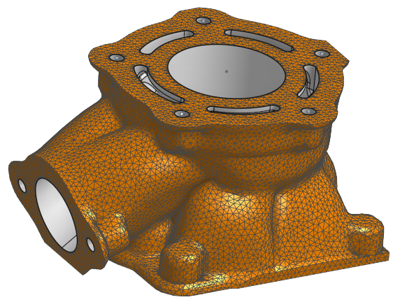
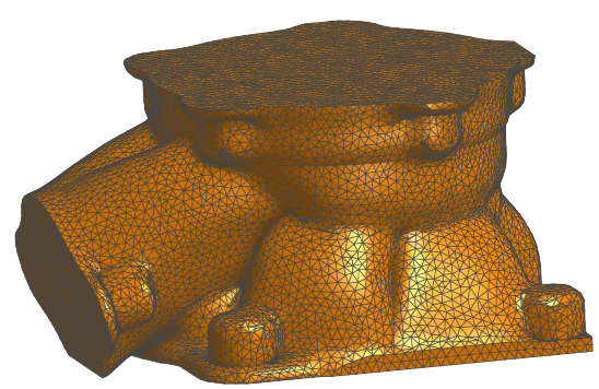
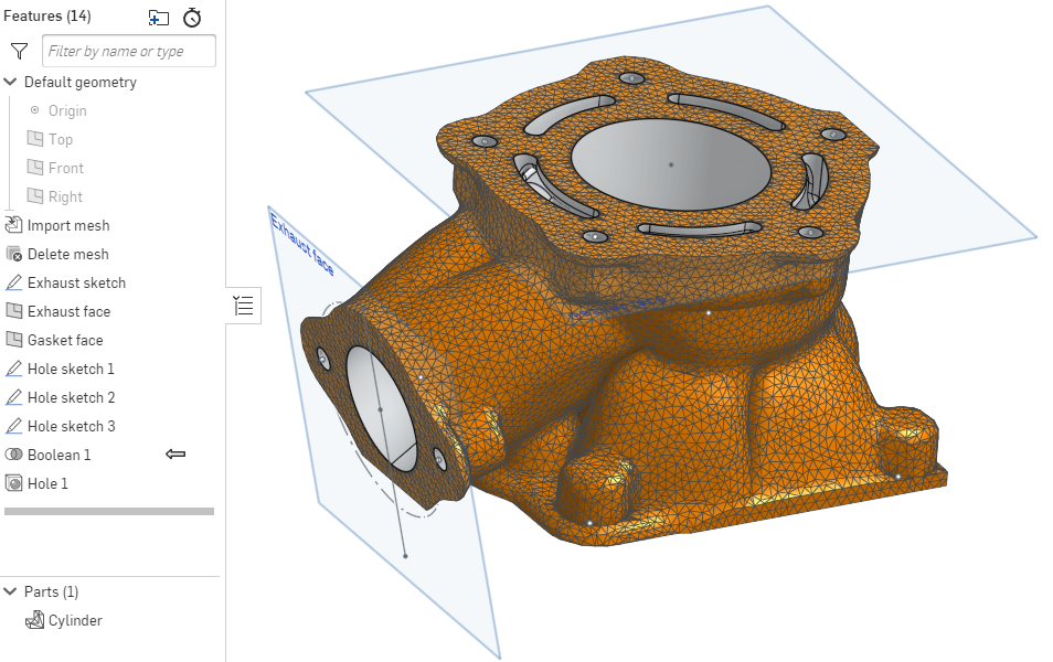
この図は、Part Studio で標準の Onshape フィーチャーが追加された、インポートされたメッシュボディを示しています。

これを実現するために、次の一連の手順を実行しました。
-
メッシュファイルを Onshape の Part Studio にインポートします。
メッシュファイル (および混合モデルファイル) は、x_t および xmm_txt を含む zip ファイル、x_b および xmm_bin を含む zip ファイル、x_b ファイル、および STL、OBJ、Rhino ファイルとしてインポートできます。

-
ブーリアン演算、押し出し、穴などの追加のモデリング操作を実行して、下のモデルの内部をグレー表示することで、正確な CAD ジオメトリを作成します。

上の画像に示すように、インコンテキストモデリングも使用できます (ブーリアン演算フィーチャーに注目してください)。
パーツリストで、アイコンはパーツが混合モデルであることを示スことに留意してください。![]()
メッシュサーフェスはそれらのアイコンとともにリストされます。![]()
アセンブリへの挿入
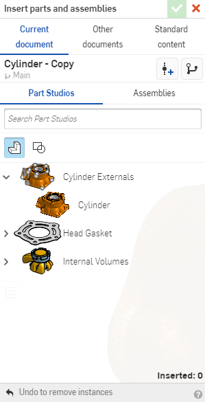
アセンブリに挿入すると、[パーツとアセンブリの挿入] ダイアログに、[パーツ] フィルターと [サーフェス] フィルター内のメッシュおよび混合モデリングパーツがリストされます。メッシュモデルや混合モデルには特別なフィルターはありません。

上の図では、[パーツ] フィルターを選択すると、メッシュの円柱が一覧表示されます。
混合モデルは、COLLADA、STL、Parasolid 形式でのみエクスポートできます。Parasolid にエクスポートする場合、パーツまたは Part Studio のエクスポートは、x_t ファイルと xmm_txt ファイルを含む zip ファイルです。エクスポートされたアセンブリは、x_t ファイルおよび xmm_txt ファイルを含む zip ファイル、または x_t ファイルおよび x_b ファイルを含む zip ファイルです。
アセンブリが次のようにエクスポートされる場合は、以下のようになります。
-
OBJ 形式 - エクスポートファイルは、.mtl ファイルと .obj ファイルを含む zip ファイルです。
-
STL 形式 - エクスポートファイルは .stl ファイルです。
-
GLTF 形式 - エクスポートファイルは .gltf ファイルです。
-
COLLADA 形式 - エクスポートファイルは .dae ファイルです
-
PVZ、IGES、ACIS - エクスポートファイルではメッシュ形式が除外されます。
-
JT - エクスポートファイルは .jt ファイルです。
-
ステップ - STEP バージョン AP242 以降では、混合要素は同じままで、古いバージョンでは除外されています。エクスポートファイルは .step ファイルです。