 歯車リレーション
![]()
![]()
![]()
回転の自由度で 2 つの合致を関連付けます。リレーションは、合致間の回転角の比率を一定に作成します。いずれかの合致パーツを移動すると、もう一方のパーツは回転して移動します。
歯車の合致関係は、回転自由度を持つ 2 つの合致を関連付けます。一方のコンポーネントが回転すると、もう一方のコンポーネントも回転します。結果として生じる回転のマグニチュードは、歯車リレーション内で定義されるギア比に依存します。歯車リレーションを定義するには、回転自由度を許容する合致関係を定義したアセンブリに 2 つの構成部品が必要です。
これには、回転合致、円筒合致、平面合致、ピンスロット合致、または平行合致が含まれます。歯車リレーションを選択し、歯車リレーションでどの 2 つの合致歯車リレーション関連付けるかを指定します。次に、関係比率を定義します。これは通常、望ましいギア比です。
歯車のギア比は、駆動歯車または入力歯車の歯数を被駆動歯車または出力歯車の歯数で割ったものとして定義されます。逆方向オプションを選択して比率を逆にすることもできます。この例では、駆動歯車の歯数は 20 個、被駆動歯車の歯数は 40 で、比率は 0.5 です。この比率は、入力シャフトと出力シャフトのキー付きスロットを確認すると視覚的に明らかになります。
入力軸が 1 回転すると、出力軸は 1 回転を完了します。歯車合致の関係は、歯車以外の回転に関連するコンポーネントにも使用できます。特定の比率で互いに回転する必要がある 2 つのコンポーネントは、歯車リレーションで定義できます。たとえば、プーリーシステムのホイールは、設定された比率で互いに回転します。
別の例としては、時計の針があります。歯車の合致関係は、特に 2 つ以上の歯車で構成されるドライブトレインを含む複雑なアセンブリの動作を解析するうえで重要です。構成部品が微調整されてアセンブリが完成し、生成されたモーションが検証されます。
歯車リレーションを追加するには、次の手順に従います。
-
 をクリックします。
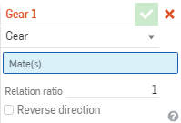
- ダイアログで、[歯車] が選択されていることを確認します。
- 合致フィーチャーのメインリスト (または現在のサブアセンブリのいずれかのフィーチャーリスト) で、2 つの合致(回転自由度が 1 度) を選択します。許容される合致点は、回転、円柱、平面、平行です (回転合致は歯車に必要な自由度と同じです)。
歯車リレーションで円筒合致、平面合致、平行合致を使用するパーツ/サブアセンブリでは、それらを所定の位置に保つために追加の合致が必要です。
- 目的のギア比を入力します。
- 必要に応じてボックスをオンにして、方向を反転します。
リレーションの自由度を選択すると、ダイアログから合致を削除するか、合致タイプを変更するか、合致を削除して最初からやり直すのでなければ、リレーションの自由度を変更することはできません。
手順
歯車リレーションを追加するには、次の手順に従います。
- 歯車リレーションアイコン (
 ) をタップします。
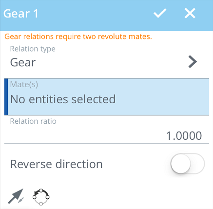
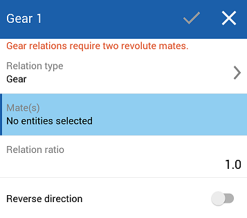
- ダイアログで、[歯車] が [リレーションタイプ] フィールドで選択されていることを確認します。
- 合致フィーチャーのメインリスト (または現在のサブアセンブリのいずれかのフィーチャーリスト) で、2 つの合致 (回転自由度が 1 度) を選択します。許容される合致点は、回転、円柱、平面、平行です (回転合致は歯車に必要な自由度と同じです)。
歯車リレーションで円筒合致、平面合致、平行合致を使用するパーツ/サブアセンブリでは、それらを所定の位置に保つために追加の合致が必要です。
- 目的のギア比を入力します。
- 必要に応じて、スライダーをタップして方向を反転します。
- チェックマークをタップします。
リレーションの自由度を選択すると、ダイアログから合致を削除するか、合致タイプを変更するか、合致を削除して最初からやり直すのでなければ、リレーションの自由度を変更することはできません。
手順
ラックアンドピニオンリレーションを追加するには、次の手順に従います。
-
をタップします。
-
ダイアログで、[歯車] が [リレーションタイプ] フィールドで選択されていることを確認します。
- 合致フィーチャーのメインリスト (または現在のサブアセンブリのいずれかのフィーチャーリスト) で、2 つの合致 (回転自由度が 1 度) を選択します。許容される合致点は、回転、円柱、平面、平行です (回転合致は歯車に必要な自由度と同じです)。
歯車リレーションで円筒合致、平面合致、平行合致を使用するパーツ/サブアセンブリでは、それらを所定の位置に保つために追加の合致が必要です。
-
目的のギア比を入力します。
-
必要に応じて、スライダーをタップして方向を反転します。
-
チェックマークをタップします。
リレーションの自由度を選択すると、ダイアログから合致を削除するか、合致タイプを変更するか、合致を削除して最初からやり直すのでなければ、リレーションの自由度を変更することはできません。