 Loft di lamiera
![]()
![]()
![]()
Il supporto iOS e Android per la funzione Loft di lamiera è limitato alla visualizzazione dei loft creati nella piattaforma desktop (browser).
Disponibile in: Part Studio
Crea una parte in lamiera che passa da un profilo all'altro.
Per creare un loft di lamiera:
- In un Part Studio fai clic sul pulsante Loft di lamiera (
 ).
).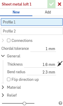
- Seleziona Nuovo per creare una nuova parte in lamiera oppure seleziona Aggiungi per aggiungere il loft a una parte esistente.
- Con il cursore nel campo Profilo 1 seleziona il profilo iniziale (regione, faccia, bordo o punto).
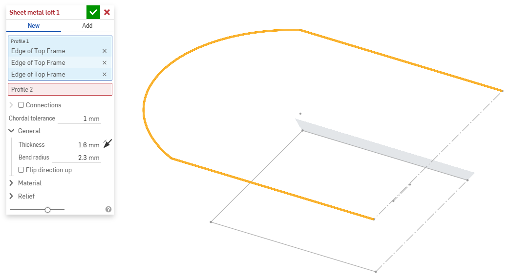
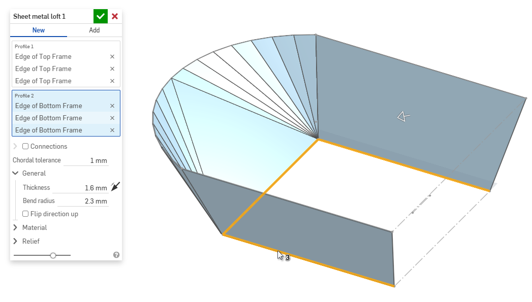
- Con il cursore nel campo Profilo 2 seleziona il profilo finale. Onshape crea un modello lamiera tra i due profili.
- Fai clic sulla casella di controllo Connessioni per un maggiore controllo sulla torsione del modello risultante. Onshape stima la prossimità all'interno dei vertici/bordi esistenti se non è specificata alcuna corrispondenza.
- Seleziona un vertice o un bordo dal loft e trascina i manipolatori per regolare la connessione.
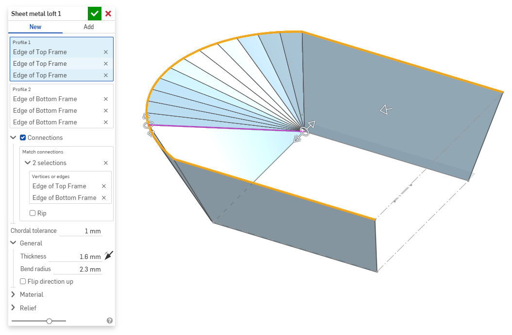
- Per dividere il modello in parti separate al momento della connessione, seleziona Fessurazione.
- Seleziona un vertice o un bordo dal loft e trascina i manipolatori per regolare la connessione.
- Usa il campo Tolleranza cordale per impostare la distanza massima a cui la geometria tassellata può variare dalla superficie sottostante.
- Quando crei nuovi modelli lamiera, puoi anche espandere le seguenti sezioni per perfezionare ulteriormente il modello:
- Generale:
- Spessore: spessore della lamiera. Fai clic sulla freccia per invertire la direzione.
- Raggio della piega: il raggio interno delle pieghe create.
- Inverti direzione verso l'alto: seleziona l'opzione per invertire l'orientamento di modello lamiera e vista piatta. Questo risulta utile per definire se le curve sono in alto o in basso rispetto al modello.
- Materiale (le opzioni in questa sezione sono identiche a quelle fornite nella funzione Modello lamiera):
- Calcolo della piegatura - Determina come vengono calcolate le piegature. Le opzioni sono:
- Fattore K (impostazione predefinita) - Utilizza il rapporto tra l'asse neutro e lo spessore del materiale.
- Tolleranza di piega - Utilizza la lunghezza dell'arco della linea neutra tra i punti tangenti di una piegatura.
- Deduzione piega: utilizza la differenza tra la somma delle lunghezze della flangia (dal bordo all'apice) e la lunghezza piatta iniziale.
Il calcolo della piegatura selezionato qui viene utilizzato come colonna nella tabella della lamiera. Ogni piegatura può essere personalizzata e modificata direttamente dalla tabella. Vedi Tavolo in lamiera e vista piatta per ulteriori informazioni.
- Fattore K piega predefinito: la frazione dello spessore del materiale su cui giace l'asse neutro di una piega. (L'impostazione predefinita è 0,45).
- Fattore K calandratura: la frazione di spessore del materiale su cui l'asse neutro si trova su una sezione di parete arrotolata. (Il valore predefinito è 0,5.)
- Calcolo della piegatura - Determina come vengono calcolate le piegature. Le opzioni sono:
- Rilievo (le opzioni di questa sezione sono identiche a quelle fornite nella funzione Modello lamiera):
- Gap minimo: il più piccolo spazio tra i bordi della lamiera che definiscono una fessurazione.
- Tipo di scarico angolo:
- Quadrato - Dimensionato
Vista piatta:
 Vista 3D:
- Rettangolo - Scalato
Vista semplice:
 Vista 3D:
- Rotondo - Dimensionato
Vista piatta:
 Vista 3D:
- Round - Scalato
Vista piatta:
 Vista 3D:
- Closed
Vista semplice:
 Vista 3D:
- Semplice
Vista piatta:
 Vista 3D:
- Quadrato - Dimensionato
- Scala scarico angolo: la scala dell'apertura angolare (per angoli scalati); un valore compreso tra 1,00 e 2,00.
- Tipo di scarico piega: la forma dello scarico piega:
- Rettangolo, in scala
- Forma oblunga - In scala
- Strappo
- Rettangolo, in scala
- Scala profondità scarico: un valore compreso tra 1,00 e 5,00. Una volta inserito un valore, questo diventa il valore predefinito in tutti i documenti.
- Un valore di 1 fa sì che uno scarico piega appiattito tocchi perfettamente la piega e uno scarico piega rettangolare corrisponda alla profondità del cilindro appiattito.
- Qualsiasi valore oltre 1 aggiunge profondità tramite la formula:
(depth scale -1) * bendRadius
- Scala larghezza scarico: un valore compreso tra 0,0625 e 2,00. Una volta inserito un valore, questo diventa il valore predefinito in tutti i documenti. La larghezza dello scarico è calcolata tramite la formula:
thickness * width scale.
- Generale:
- Quando aggiungi materiale a un modello lamiera esistente, fai clic sul campo Ambito unione, quindi seleziona la parte a cui aggiungere materiale. L'ambito unione può accettare solo corpi di un singolo modello lamiera attivo.
Quando un modello di lamiera è attivo (durante la creazione o la modifica), sono disponibili strumenti aggiuntivi:
-
 flangia - Crea un muro per ogni bordo selezionato, collegato allo spigolo selezionato con una piega.
 -
 Orlo: crea un orlo per ogni bordo o faccia selezionati, su una lamiera esistente.
 -
 Tab - Aggiungere una linguetta a una flangia in lamiera.
 -
 Curva - Piegate un modello in lamiera lungo una linea di riferimento, con opzioni di controllo della piegatura aggiuntive.
 -
 Forma: crea funzioni forma su modelli di lamiera esistenti. Le forme sono selezionabili nel documento corrente, in altri documenti o in una libreria predefinita di forme in lamiera.
 -
Loft: crea modelli in lamiera che collegano due profili.
-
 Crea un giunto - Convertite l'intersezione di due pareti in una caratteristica di giunzione, una piegatura (pareti unite da una geometria cilindrica) o uno strappo (piccolo spazio tra due pareti).
 -
 Angolo - Modificate il tipo di angolo e la scala di rilievo.
 -
 Rilievo di pieg - Modificare un rilievo di piegatura (il piccolo taglio eseguito nel punto in cui l'estremità della piega incontra lo spigolo libero), la profondità e la larghezza del rilievo.
 -
 Modificare il giunto - Apporta modifiche a un giunto esistente, ad esempio convertendo una piegatura in uno strappo. Attualmente disponibile nella tabella di visualizzazione piatta.
 -
 Interruzione spigolo: interrompe lo spigolo sulle parti in lamiera esistenti applicando un raccordo o uno smusso. Seleziona un bordo o vertice d'angolo e specifica il tipo e la distanza di interruzione dello spigolo. Consigliamo di utilizzare questa funzione dopo aver completato tutte le flange e gli spigoli chiusi del modello lamiera.
 -
 Tavolo in lamiera e vista piana - Aprire e chiudere le tabelle Rip/Bend e la visualizzazione dello schema piatto del modello in lamiera. Utilizzate questa tabella per convertire gli strappi in piegature e viceversa.
 -
 Disattiva modello lamiera: chiude (disattiva) il modello lamiera; crea una funzione nell'elenco funzioni.