Rayures zébrées
![]()
Disponible dans : Esquisse, Part Studio, Assemblage
Les rayures zébrées représentent le reflet d'une pièce rayée sur le modèle, les faces ou les surfaces actuels d'un Atelier des pièces ou d'un Assemblage. Cela vous permet de voir si la courbure des arêtes est alignée et continue.
-
Cliquez sur l'icône Afficher les outils d'analyse (
 ) dans le coin inférieur droit de l'interface.
 -
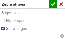
Dans le menu, sélectionnez Rayures zébrées pour ouvrir la boîte de dialogue :
-
Nombre de bandes - Nombre de bandes de courbure affichées sur chaque surface
-
Inverser les rayures - Inverse les rayures.
-
Afficher les arêtes - Affiche les arêtes entre les faces de la pièce (par défaut). Lorsque cette option est décochée, les arêtes de la pièce sont masquées Le masquage de ces arêtes améliore la visualisation des courbes entre les faces des pièces dans certaines situations.
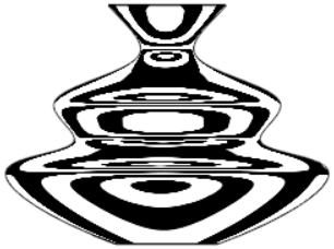
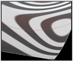
Lorsque la courbure est alignée une arête, celle-ci est lisse et les rayures s'alignent, puis s'écartent de l'arête :
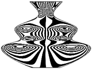
Lorsque la courbure est continue de part et d'autre d'une arête, l'arête est lisse et il n'y a aucun changement de courbure de part et d'autre de l'arête. Les rayures s'alignent et ne s'écartent pas de l'arête :
Lorsque vous acceptez la boîte de dialogue Rayures zébrées (cliquez sur la coche), la boîte de dialogue se ferme et les rayures sont conservées. Pour désactiver les rayures zébrées, sélectionnez à nouveau Rayures zébrées dans le menu Afficher les outils d'analyse et cliquez sur le X dans la boîte de dialogue. (La sélection de la palette de couleurs dans le menu Visualisation de la courbure désactive également les rayures zébrées).
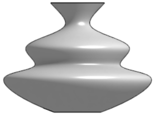
Aucune visualisation de la courbure |
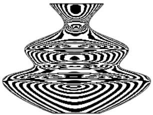
Courbure par défaut : bandes 35 |
|
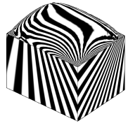
10 bandes |
35 bandes ; inversées |