Analyse de l'épaisseur
![]()
Disponible uniquement pour
Disponible dans : Part Studio
Utilisez l'Analyse de l'épaisseur pour mesurer la quantité de matériau distribuée dans chaque zone d'une pièce.
Actuellement, seuls les pièces Onshape natives et les types de modèles de maillage sont pris en charge. Les composites fermés ne sont pas pris en charge pour le moment.
Dans un Part Studio contenant au moins une pièce :
-
Cliquez sur le bouton Afficher les outils d'analyse (
 ) dans le coin inférieur droit de la zone graphique. Dans le menu, sélectionnez Analyse de l'épaisseur pour ouvrir la boîte de dialogue :
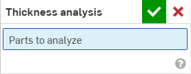
-
Sélectionnez une ou plusieurs pièces à analyser.
Onshape commence instantanément à calculer la demande d'analyse d'épaisseur. Le pointeur de progression situé en bas à gauche de la zone graphique fournit une mise à jour sur l'état de l'analyse :
-
Préparation de l'analyse d'épaisseur - La géométrie est discrétisée et traitée pour analyse
-
Analyse de l'épaisseur du traitement - Des instances cloud hautes performances sont provisionnées
-
Calcul de l'épaisseur - Le calcul de l'analyse de l'épaisseur commence
-
Analyse d'épaisseur d'affinage - Les premiers résultats sont disponibles et les résultats de meilleure fidélité continuent à être traités
-
Analyse d'épaisseur après traitement - Les résultats finaux sont en cours de traitement et seront bientôt disponibles
-
-
Cliquez sur la coche verte pour valider votre sélection et fermer la boîte de dialogue. L'outil d'analyse d'épaisseur reste actif. Lorsque les résultats de l'analyse d'épaisseur initiale sont disponibles, la barre de couleur s'ouvre dans la zone graphique :
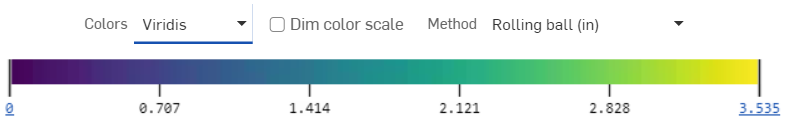
Les pièces sélectionnées s'affichent automatiquement. La barre de couleurs associe les valeurs des champs aux couleurs affichées le long de la surface de votre pièce (ou de vos pièces).
-
Pour modifier la palette de couleurs, sélectionnez une palette dans la liste déroulante Couleurs.
-
Pour modifier la plage de la barre de couleurs, sélectionnez la valeur de la limite inférieure ou supérieure et saisissez un nouveau nombre. Utilisez le bouton d'actualisation pour rétablir la limite à la valeur la plus basse/la plus élevée du champ mesuré.
Vous pouvez également cliquer et faire glisser la coche au-dessus de la valeur de la limite inférieure ou supérieure et la faire glisser vers une nouvelle position dans la légende. Repositionnez entièrement la barre de couleur en la survolant avec le curseur jusqu'à ce qu'elle soit active, puis cliquez et faites glisser la légende vers une nouvelle position sur votre écran.
À moins d'être ajustées manuellement, les limites de la légende peuvent s'ajuster automatiquement à de nouvelles limites tandis que les résultats de l'analyse d'épaisseur intermédiaire sont affinés. Une fois ajustées manuellement, les mises à jour intermédiaires n'entraîneront aucune modification des limites supérieures ou inférieures. Cependant, les valeurs situées le plus loin le long de la barre de couleur peuvent être mises à jour à mesure que de nouvelles informations sont disponibles.
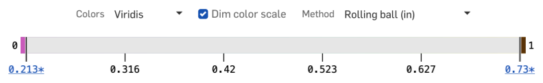
La légende affiche des couleurs uniques pour les valeurs de champ situées en dehors des limites définies par l'utilisateur. Cochez l'option Échelle de couleurs atténuées pour créer une vue en 3 couleurs et évaluer rapidement les régions situées en dehors de votre plage cible.
-
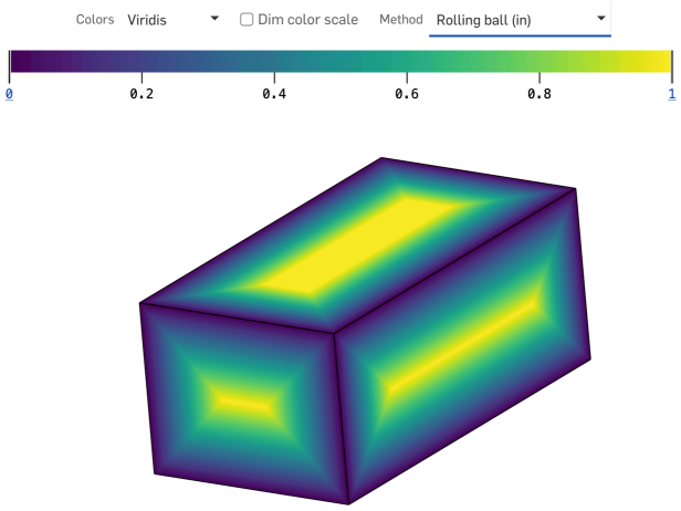
Sélectionnez le champ préféré dans le menu déroulant Méthode :
-
Bille roulante
-
Gradient de bille roulante (%)
-
Rayon
-
Gradient de rayons (%)
Vous pouvez continuer à travailler normalement dans l'Atelier des pièces tout en utilisant l'analyse d'épaisseur. L'évaluation de l'épaisseur est automatiquement mise à jour au fur et à mesure que vous apportez des modifications.
-
-
Pour modifier l'analyse d'épaisseur, cliquez sur le bouton Afficher les outils d'analyse (
) en bas à droite de la zone graphique et sélectionnez Modifier l'analyse d'épaisseur dans le menu. -
Pour désactiver l'analyse de l'épaisseur, cliquez sur Afficher les outils d'analyse (
) et sélectionnez Désactiver l'analyse de l'épaisseur.
La méthode de l'épaisseur de la bille roulante calcule la taille de la plus grande sphère pouvant être inscrite dans une pièce à chaque point de la surface de la pièce.
La sphère est tangente au point d'inspection et à au moins un autre point de la pièce (bien qu'elle puisse être tangente à plusieurs pièces) et est donc censée rouler le long de l'intérieur de la pièce tout en changeant simultanément de taille. L'épaisseur mesurée est rapportée comme le diamètre de la sphère inscrite.
Remarques
-
La méthode d'épaisseur de la bille roulante fournit une mesure d'épaisseur définie par des relations géométriques localisées et non triviales en plus d'un point de la zone d'intérêt.
-
La distribution de l'épaisseur de la bille roulante est garantie d'être continue dans toutes les zones de toute pièce solide.
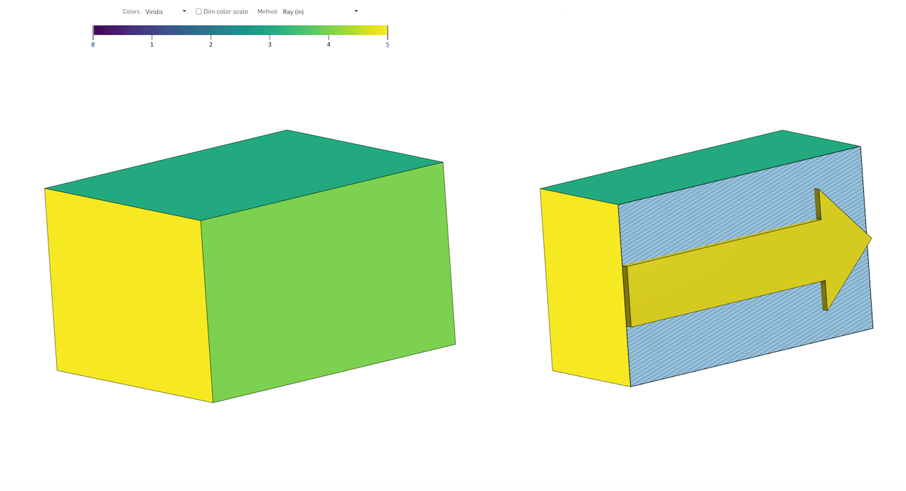
La méthode d'épaisseur des rayons calcule la distance parcourue le long d'une trajectoire en ligne droite à travers l'intérieur d'une pièce.
À chaque point de la surface de la pièce, un rayon est projeté perpendiculairement à cette surface et se termine lors de la première intersection en un autre point le long de la pièce. La longueur du segment de ligne entre ces deux points correspond à l'épaisseur du rayon.
Remarques
-
Une ligne projetée perpendiculairement à un point le long de la surface d'une pièce ne garantit aucune relation géométrique avec la surface en son second point.
-
La distribution de l'épaisseur des rayons est rarement continue sur l'ensemble de la pièce. Il contiendra de fortes discontinuités, surtout à proximité des angles vifs.
La méthode de gradient d'épaisseur mesure la rapidité avec laquelle l'épaisseur d'une pièce est modifiée lorsque l'on se déplace le long de la surface de cette pièce. La valeur elle-même est le ratio (A/B) des termes suivants :
-
La quantité maximale que cette épaisseur peut augmenter ou diminuer lorsque l'on se déplace (nominalement et instantanément) dans n'importe quelle direction à partir d'un point de la surface de la pièce, mesurée en unités de longueur.
-
La distance géodésique nominalement instantanée parcourue dans cette direction, mesurée dans les mêmes unités de longueur.
Le ratio est non dimensionnel, non négatif et présenté en pourcentage (%) hors convention.