Aplatir les surfaces
![]()
Disponible dans : Esquisse, Part Studio
Aplatir les surfaces génère une surface planaire à partir d'une ou de plusieurs surfaces non planaires contiguës.
L'outil effectue un aplatissement géométrique pour créer une surface avec une énergie de déformation minimale.
L'opération d'aplatissement ignore les propriétés du matériau de la pièce dont la surface est mise à plat. La surface obtenue ne possède aucune propriété matérielle.
Quelques utilisations pour aplatir les surfaces :
-
Évaluer la forme plate (découpée) d'un masque de peinture appliqué sur une certaine zone d'une pièce.
-
Évaluer la faisabilité d'appliquer une décalcomanie sur une zone incurvée d'une pièce sans effort ni froissement excessifs.
-
Déterminer la forme découpée d'un pli composite en fonction de la ligne de moulage extérieure (OML) et du contour du pli.
-
Ajouter des fonctions (découpes, courbes de texte, enveloppements de texte) à la surface plane et leur redonner la forme de la surface incurvée.
Les fabricants et les assembleurs appliquent souvent des décalcomanies, des habillages ou des revêtements sur des surfaces. Bien que ceux-ci proviennent généralement de feuilles planes, les surfaces sur lesquelles ils adhèrent ne sont pas toujours planes. L'outil Aplatir les surfaces d'Onshape génère une surface plane à partir d'une ou plusieurs surfaces non planes contiguës, ce qui permet une application plus fluide.
Lorsque vous appliquez une feuille plane sur une surface non plane, elle s'étire et se comprime inévitablement. L'outil Aplatir les surfaces d'Onshape effectue un aplatissement géométrique pour créer une surface avec une énergie de déformation minimale.
Une surface mise à plat ne tient pas compte de la définition du matériau. La surface mise à plat qui en résulte ne possède aucune propriété matérielle.
Ce manche de raclette nécessite un revêtement texturé.
Dans l'Atelier des pièces, cliquez sur l'icône Afficher les outils d'analyse dans le coin inférieur droit de la zone graphique. Sélectionnez Aplatir les surfaces.
Sélectionnez une ou plusieurs faces contiguës à aplatir. Cliquez ensuite sur le bouton Aplatir pour effectuer l'opération de mise à plat.
L'outil Aplatir les surfaces fournit plusieurs visualisations pour le feedback. Afficher les facettes révèle les facettes du maillage à la fois sur la surface d'origine et sur la surface mise à plat.
Lorsque l'option Afficher les facettes est désactivée, Afficher les arêtes permet d'afficher les arêtes sur la surface mise à plat.
Afficher damier affiche une répétition en damier à la fois sur la surface d'origine et sur la surface mise à plat. Ajustez l'échelle de la répétition en entrant l'échelle du damier. Les valeurs faibles créent des blocs de damier plus grands, et les valeurs élevées créent des blocs plus petits.
Afficher la distorsion affiche les zones de la surface mise à plat que le processus d'aplatissement déforme de façon géométrique. Les zones présentant une distorsion sont affichées en rouge ou en bleu. Le bleu indique une tension ou un étirement, et le rouge indique une compression ou un froissement. Les zones de couleur plus forte indiquent les zones présentant des valeurs de distorsion plus élevées.
Cochez Afficher mise à plat pour afficher la surface résultante.
Sélectionnez une origine par rapport à laquelle vous souhaitez aplatir la surface. Si vous ne sélectionnez aucune origine, Onshape en choisit automatiquement une pour la surface mise à plat.
Positionnez davantage la surface mise à plat en saisissant une valeur de décalage mis à plat ou d'angle mis à plat.
L'outil Aplatir les surfaces ne crée pas de pièce dans la liste des pièces. Cochez Afficher les contrôles d'exportation pour afficher les options d'exportation. Exportez la surface mise à plat vers Parasolid ou STL pour obtenir une représentation physique de la surface dans un fichier. Si nécessaire, le fichier peut ensuite être réimporté dans l'Atelier des pièces à l'aide de la fonction dérivée.
Vous pouvez également sélectionner votre format d'exportation au format SVG ou DXF, puis cliquer sur le bouton Exporter pour envoyer le fichier sur votre appareil. Vous pouvez ensuite travailler sur la décalcomanie dans votre logiciel externe, par exemple Adobe Illustrator.
Un examen minutieux de cette surface mise à plat révèle une distorsion importante au bas du manche. Quittez l'outil Aplatir les surfaces et appliquez une fonction Scinder pour ajouter des arêtes supplémentaires à la face.
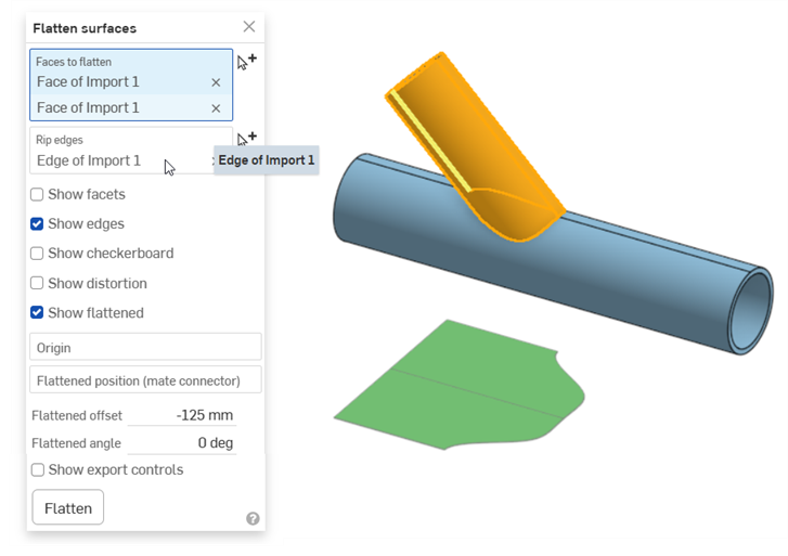
Sélectionnez Aplatir les surfaces et sélectionnez une arête pour les arêtes déchirées. Cliquez sur Aplatir. La surface mise à plat a été scindée ou déchirée le long de l'arête sélectionnée, ce qui atténue la tension due à l'étirement et au froissage.
Dans un Atelier des pièces :
-
Cliquez sur l'icône Afficher les outils d'analyse (
 ) dans le coin inférieur droit de la zone graphique. Dans le menu, sélectionnez Aplatir les surfaces pour ouvrir la boîte de dialogue :
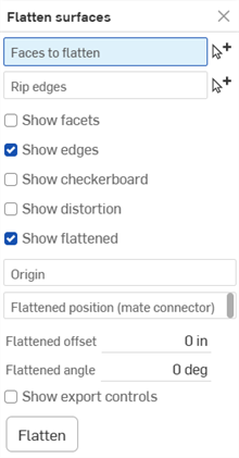
-
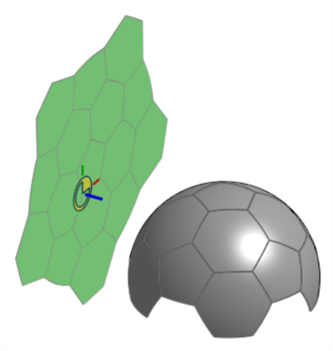
Le champ Faces à aplatir étant sélectionné, sélectionnez une ou plusieurs faces contiguës dans la zone graphique.
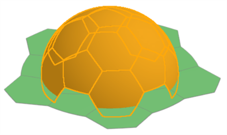
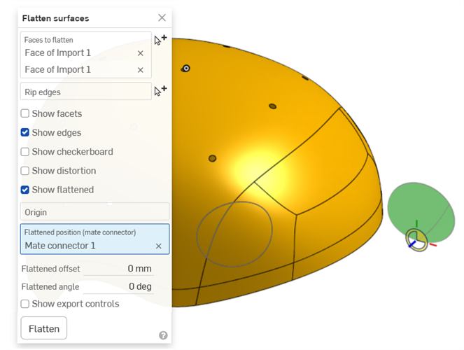
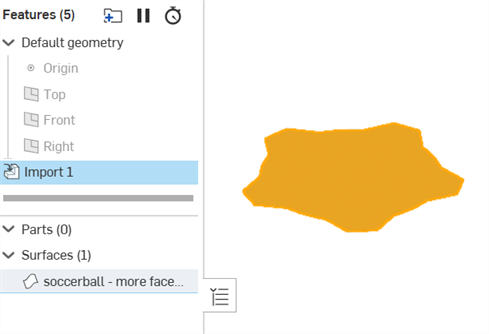
Exemple de mise à plat partielle d'un ballon de football. Notez que vous devez d'abord appuyer sur le bouton Aplatir pour afficher les résultats.
-
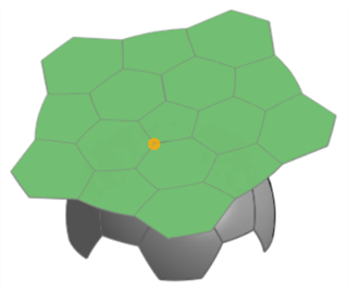
Cliquez pour sélectionner le champ Déchirer des arêtes dans la boîte de dialogue, puis sélectionnez les arêtes de la zone graphique où la surface mise à plat doit être déchirée.
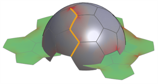
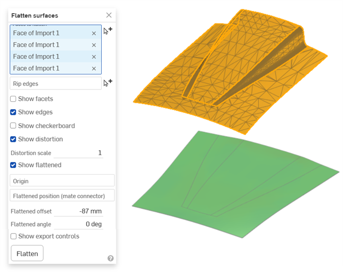
Exemple d'arêtes déchirées utilisées. Notez que cela permet de réduire la distorsion de la surface mise à plat. Comparez avec l'image affichée dans l'option Afficher la distorsion ci-dessous.
-
Vérifiez les paramètres d'affichage facultatifs suivants et entrez les valeurs d'entrée appropriées :
-
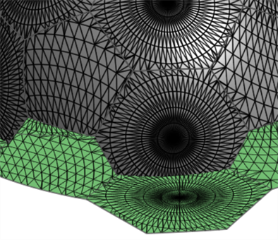
Afficher les facettes - Cochez cette case pour afficher les facettes du maillage à la fois sur la surface d'origine et sur la surface mise à plat.
-
Afficher les arêtes - Par défaut, les arêtes des surfaces mises à plat sont visibles. Décochez cette case pour masquer ces arêtes.
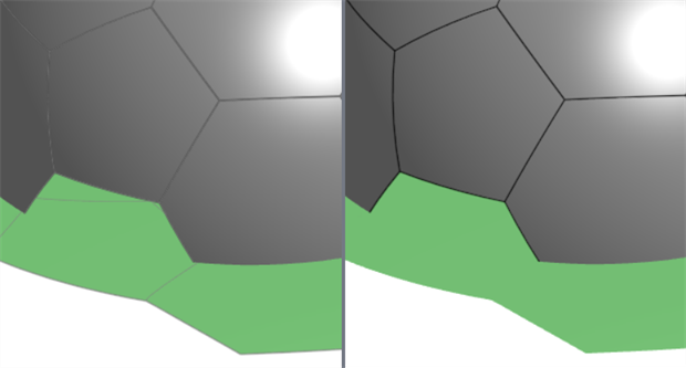
Afficher les arêtes activé (à gauche) et désactivé (à droite)
-
Afficher le damier - Cochez cette case pour afficher une répétition en damier noir et blanc superposée à la fois à la surface d'origine et à la surface mise à plat.
-
Échelle de damier - Définit l'échelle de répétition en damier. Des valeurs plus faibles se traduisent par des blocs à répétitions plus grands. Des valeurs plus élevées se traduisent par des blocs à répétitions plus petits.
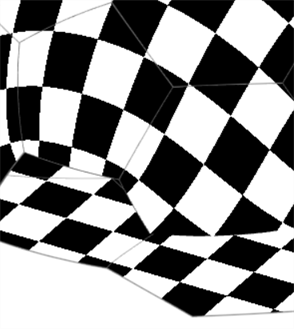
Afficher le damier ; échelle de damier : 25
-
-
Afficher la distorsion - Affiche les zones de la surface mise à plat présentant une distorsion géométrique résultant du processus d'aplatissement en magenta. Plus la couleur est forte, plus la distorsion est importante.
-
Échelle de distorsion - Définit le niveau de sensibilité de distorsion qui est signalé. Des valeurs plus élevées augmentent la sensibilité à la distorsion (signalant une distorsion plus importante). Des valeurs plus faibles diminuent la sensibilité à la distorsion (signalant une moindre distorsion).

-
-
Afficher mise à plat - Affiche le résultat aplati. Cela vous permet d'afficher ou non le résultat mis à plat.
-
Position mise à plat (connecteur de positionnement) - Sélectionnez un connecteur de positionnement pour positionner le résultat de la surface mise à plat à un emplacement autre qu'en dessous des surfaces sélectionnées.
-
Décalage mis à plat - Si un connecteur de positionnement est utilisé pour la position mise à plat, entrez une valeur numérique positive ou négative pour décaler cette position le long de l'axe Z du connecteur de positionnement.
-
Angle mis à plat - Si un connecteur de positionnement est utilisé pour la position mise à plat, entrez une valeur de degré d'angle positive ou négative pour décaler cette position par rapport à l'axe Z du connecteur de positionnement.
-
-
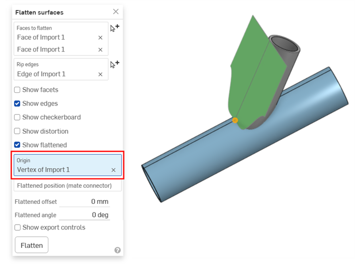
Origine - Sélectionnez un sommet utilisé comme point d'origine de la surface mise à plat obtenue.
-
-
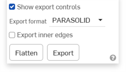
Cliquez sur Afficher les contrôles d'exportation pour afficher les options d'exportation :
-
Format d'exportation - Sélectionnez parmi une liste d'options de format de fichier : PARASOLID, STL, DXF ou SVG.
-
Exporter les arêtes intérieures - Exporte les arêtes intérieures si les faces à aplatir contiennent plusieurs faces.
Exemple
-
Bouton Exporter - Cliquez sur le bouton Exporter pour télécharger les résultats finaux de la surface mise à plat sur votre appareil.
-
-
Cliquez sur Aplatir pour afficher la surface mise à plat finale résultant des entrées de la boîte de dialogue.
Aplatir pour obtenir une surface de décalcomanie ou un masque de peinture.
L'une des utilisations de l'outil Aplatir les surfaces consiste à extraire une surface plane de plusieurs surfaces non planaires, en l'utilisant comme décalcomanie ou masque de peinture.
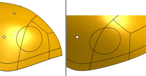
Dans l'image suivante, la vue latérale semble être un cercle parfait. En réalité, vous devrez extraire la surface incurvée, l'aplatir, appliquer une décalcomanie, puis appliquer la décalcomanie sur la surface incurvée :
Utilisation de l'outil Aplatir les surfaces pour obtenir la découpe de la décalcomanie :
Une fois que vous avez la surface, cochez Afficher les commandes d'exportation, sélectionnez SVG ou DXF comme format d'exportation, puis cliquez sur le bouton Exporter pour envoyer le fichier à votre appareil. Vous pouvez ensuite travailler sur la décalcomanie dans votre logiciel externe, par exemple Adobe Illustrator.
Exportation des arêtes intérieures
Le même exemple que ci-dessus est exporté sans et avec l'option Exporter les arêtes intérieures sélectionnée (dans la section Afficher les contrôles d'exportation de la boîte de dialogue) :
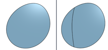
Exporter les arêtes intérieures désactivé (gauche) et activée (droite)
Aplatir un tuyau
Dans cet exemple, un tuyau est déroulé. Il s'agit d'une surface qui peut être développée et l'ajout d'une déchirure permet d'obtenir une surface plane sans distorsion :
Si vous définissez l'origine sur le sommet du tuyau, vous pouvez visualiser comment la surface s'aplatit le long de l'arête du tuyau :
Capot de voiture
Cet exemple montre la surface numérisée d'un capot de voiture importée dans Onshape sous forme de maillage. En règle générale, vous souhaitez créer un film de protection de peinture (PPF) à partir de cette surface. Ceci est utile sur les capots, les ailes, les surfaces avant des phares et autres surfaces incurvées. L'importation est mise à plat et présente peu de distorsion :
-
Certaines options nécessitent d'appuyer à nouveau sur le bouton Aplatir si elles sont mises à jour. Par exemple, si une déchirure d'arête est ajoutée ou si une origine est sélectionnée.
-
L'outil Aplatir les surfaces ne crée pas de pièce dans la liste des pièces. Exportez la surface mise à plat pour obtenir une représentation de la surface dans un fichier. Ce fichier peut ensuite être réimporté dans l'Atelier des pièces, si nécessaire.
Exemple de surface mise à plat importée. La surface a été exportée à l'aide d'un format de fichier PARASOLID, importée dans le document et importée dans un Atelier des pièces à l'aide de la fonction dérivée.
-
L'outil Aplatir les surfaces n'assure pas une précision parfaite. Vous ne devez pas l'utiliser pour obtenir des mesures critiques ou précises à des fins de calculs. Il doit être utilisé pour fournir les cotes générales nécessaires pour enrouler des objets tels que des décalcomanies autour de surfaces non planes.