Analyse de courbe/surface
![]()
Disponible dans : Esquisse, Part Studio, Assemblage
Raccourci : maj+c
L'analyse de courbe/surface permet de visualiser et d'analyser la courbure à l'aide de différentes méthodes sur une esquisse ou une pièce dans un Part Studio. Accédez à la boîte de dialogue Analyse de courbe/surface à l'aide des touches de raccourci (Maj+c), du menu contextuel d'une esquisse, d'une pièce ou d'une surface, ou via le menu Afficher les outils d'analyse situé dans le coin inférieur droit de l'interface.
En mode esquisse ou lors de la modification d'une esquisse, vous pouvez utiliser le raccourci maj+C pour sélectionner automatiquement toutes les courbes d'esquisse et ouvrir la boîte de dialogue d'analyse des courbes/surfaces. maj+C permet d'ouvrir et de fermer la boîte de dialogue tout en conservant les sélections.
L'outil d'analyse des courbes/surfaces reste ouvert même après avoir quitté l'esquisse, mais les champs de sélection ne sont pas actifs. Vous pouvez ajouter d'autres sélections ou supprimer des sélections tant que l'outil est ouvert. Toutes les modifications apportées aux sélections seront conservées la prochaine fois que vous invoquerez l'outil. Si vous effectuez une présélection avant d'ouvrir l'outil, celui-ci s'ouvre uniquement avec cette sélection, effaçant ainsi toutes les autres sélections effectuées précédemment.
Pour examiner les courbes et les surfaces, procédez comme suit :
- Cliquez sur l'icône Afficher les outils d'analyse (
 ) dans le coin inférieur droit de l'interface.
 - Sélectionnez Analyse de courbe/surface pour ouvrir la boîte de dialogue. Vous pouvez également accéder à cette boîte de dialogue en faisant un clic droit sur une esquisse ou une pièce dans la zone graphique et en la sélectionnant dans le menu contextuel :
-
Sélectionnez les arêtes et les faces à analyser. Vous pouvez également les sélectionner avant d'accéder à la boîte de dialogue.
- Select from the following options:
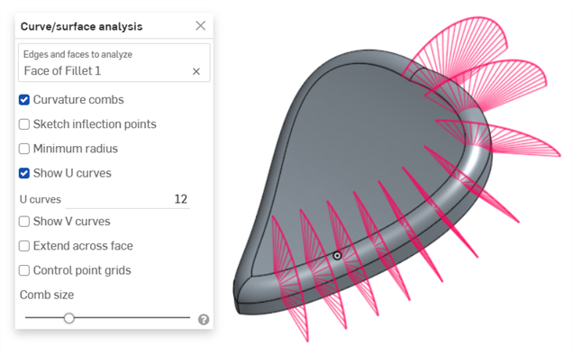
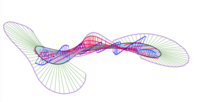
Curvature combs - Displays the combs of the selected edge(s) and/or face(s) along the U and V directions. Curvature combs are evaluated at evenly spaced isolines, not necessarily at the control points, and are used for evaluating the resultant shape of a curve/surface up to Flow (G3) continuity.
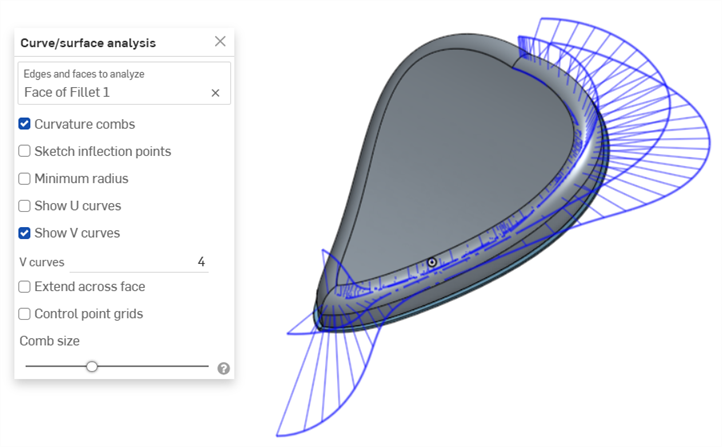
Curvature combs on the V direction on a face
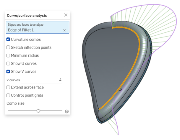
Curvature combs on an edge. Combs are shown in green, bounded in magenta.
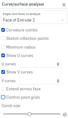
Show U curves - Displays curvature combs along the U direction. U curves are displayed in red:
Show V curves - Displays curvature combs along the V direction. V curves are displayed in blue:
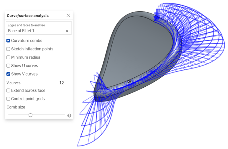
Increase or decrease the number of curves using the numeric U curves and V curves fields, from 2 to 64. The default is 8 for each.
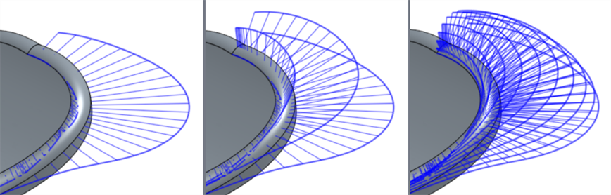
V curves set at 2 (left), 4 (middle), and 8 (right)
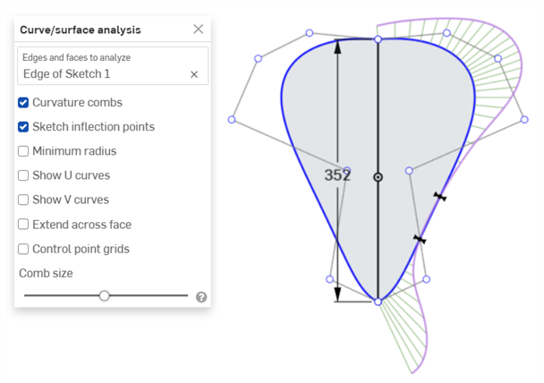
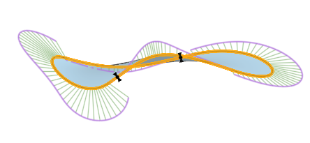
Sketch inflection points (sketch only) - Displays the inflection points along a sketch edge. They appear as black 'bow ties':
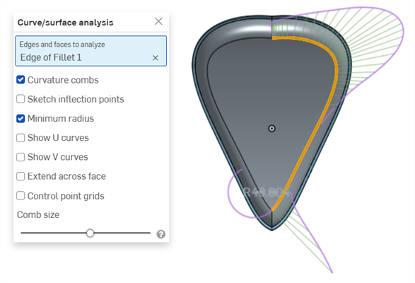
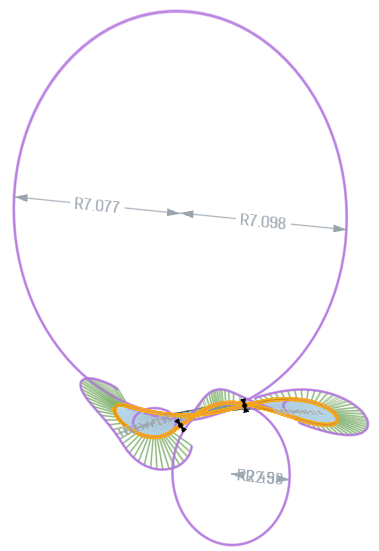
Minimum radius (edges only) - Shows the minimum radius along an edge, either a sketch or part edge:
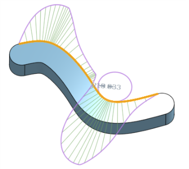
Extend across face - Extends the curvature combs along adjacent faces:
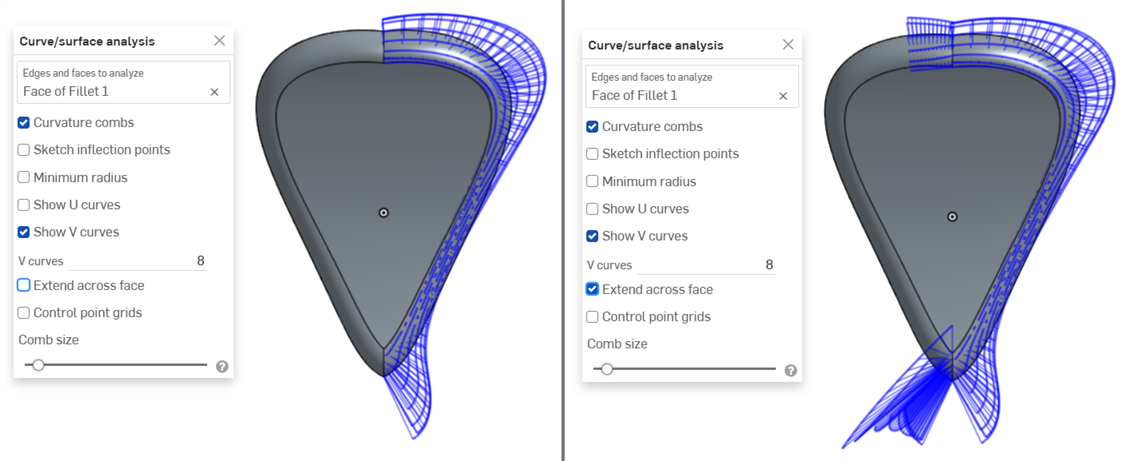
Curvature combs not extended across faces (left) and extended across faces (right)
Control point grids - Displays the control points grid for the selected edge, either a sketch or part edge. This is the location of the control points on the underlying bSpline curves that define the surface (or curve). The number and distribution of the control points provides important information about the underlying math defining the shape.
Dense clusters of control points indicate potential problem areas, and can be deleterious to the surface quality. In short, control point grid is used to understand the underlying mathematical definition of the surface/curve,
Control point grids are shown in magenta:
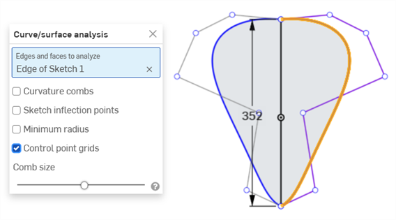
Control point grids displayed in magenta
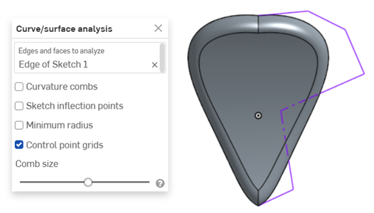
Control point grids displayed with the sketch closed and the part displayed
Knot points - Displays the knot points on the selected curve or surface. (Not available for non-spline entities such as cylindrical faces, intersection curves, offset curves, etc.)
Details - Displays details (such as degree, spans, and number of control points) upon hovering over the selected curve or surface. (Not available for non-spline entities such as cylindrical faces, intersection curves, offset curves, etc.)
Comb size - Use the slider at the bottom of the dialog to adjust the magnitude of the combs.
-
Cliquez et faites glisser une courbe pour ajuster la courbure, si nécessaire. Les peignes sont mis à jour de manière dynamique pendant que vous faites glisser.
-
Lorsque vous avez terminé, cliquez sur
 pour fermer la boîte de dialogue Analyse de courbe/surface.
Vous pouvez également afficher les champs de courbure d'une fonction en cours de traitement, par exemple lors d'une extrusion :
- Lorsque la boîte de dialogue des fonctions est ouverte, faites un clic droit sur la zone graphique et sélectionnez Analyse de courbe/surface pour ouvrir la boîte de dialogue Analyse de courbe/surface :
- Sélectionnez une courbe pour la fonction :
- Vous pouvez afficher la courbure de l'arête sélectionnée utilisée pour créer la nouvelle fonction (décochez Afficher pour les arêtes prévisualisées) ou sélectionnez Afficher pour les arêtes prévisualisées pour afficher les champs de courbure de l'arête de la nouvelle fonction en cours de création :
Vous pouvez également afficher les peignes de courbure, les points d'inflexion et le rayon minimum en cochant les cases situées à gauche de ces options dans la boîte de dialogue Afficher la courbure.
Exemple d'une fonction avec Afficher pour les arêtes prévisualisées, Afficher les peignes de courbure, Afficher les points d'inflexion et Afficher le rayon minimum sélectionnés dans la boîte de dialogue Afficher la courbure.
Pour plus d'informations sur l'analyse des courbes et des surfaces, voir Modélisation des surfaces.