 Lissage de tôlerie
![]()
![]()
![]()
La prise en charge par iOS et Android de la fonction Lissage de tôlerie est limitée à l'affichage et à la modification des lissages créés à partir de la plateforme de bureau (navigateur).
Disponible dans : Part Studio
Créez une pièce en tôle qui passe d'un profil à l'autre.
Pour créer un lissage de tôlerie :
- Lorsque vous êtes dans un Part Studio, cliquez sur le bouton Lissage de tôlerie (
 ).
).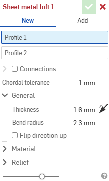
- Sélectionnez Nouveau pour créer une nouvelle pièce en tôle, ou sélectionnez Ajouter pour ajouter le lissage à une pièce existante.
- Avec un focus sur le champ Profil 1, sélectionnez le profil de départ (zone, face, arête ou point).
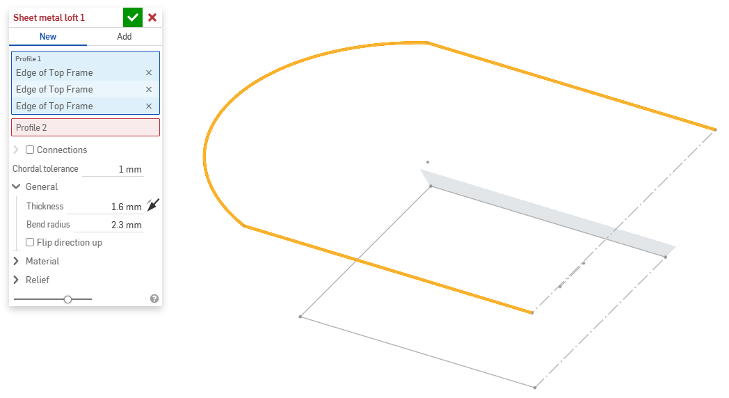
- Avec un focus sur le champ Profil 2, sélectionnez le profil de fin. Onshape crée un modèle de tôlerie entre les deux profils.
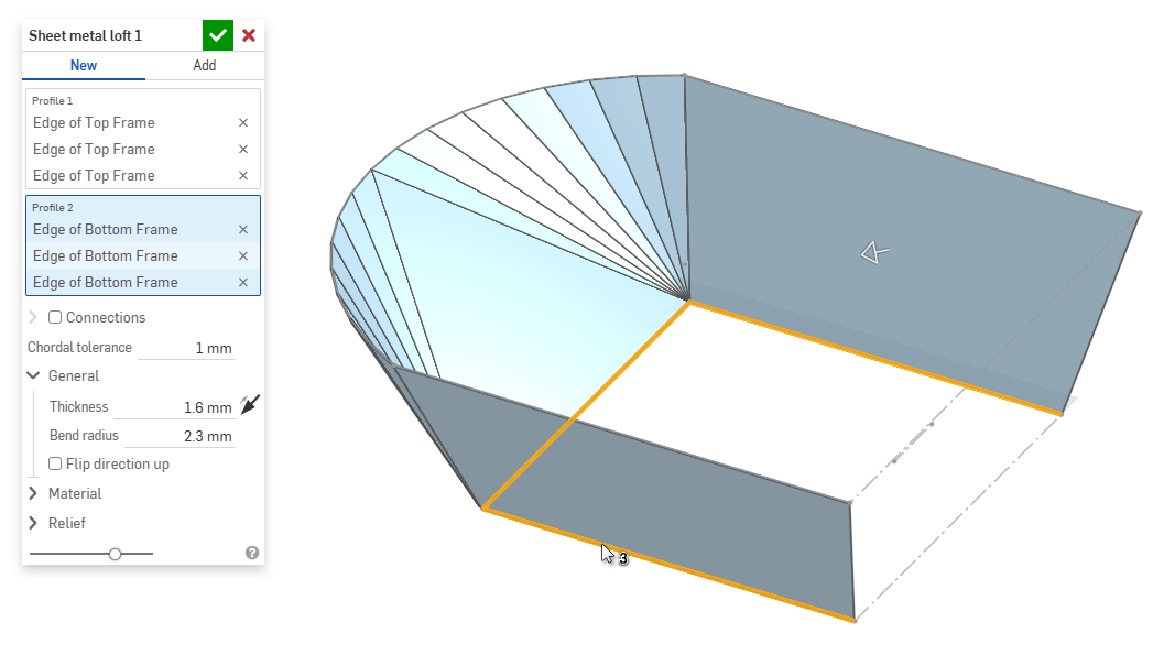
- Cochez la case Connexions pour mieux contrôler la torsion du modèle obtenu. Onshape estime la proximité entre les sommets et les arêtes existants si aucune correspondance n'est spécifiée.
- Sélectionnez un sommet ou une arête dans le lissage et faites glisser le ou les manipulateurs pour ajuster la connexion.
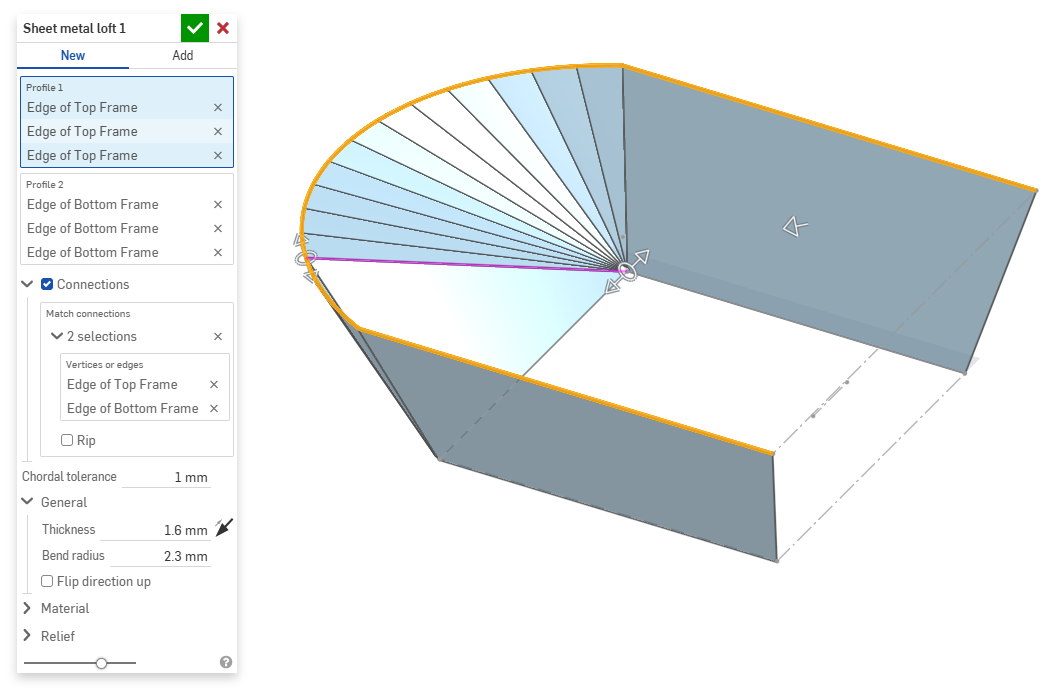
- Pour diviser le modèle en pièces distinctes au niveau de la connexion, sélectionnez Déchirure.
- Sélectionnez un sommet ou une arête dans le lissage et faites glisser le ou les manipulateurs pour ajuster la connexion.
- Utilisez le champ Tolérance de la corde pour définir la distance maximale à laquelle la géométrie facétisée peut varier par rapport à la surface sous-jacente.
- Lorsque vous créez de nouveaux modèles de tôlerie, vous pouvez également développer les sections suivantes pour affiner le modèle :
- Général :
- Épaisseur - Épaisseur de la tôlerie. Cliquez sur la flèche pour inverser la direction.
- Rayon de courbure - Rayon intérieur des plis créés
- Inverser la direction vers le haut - Sélectionnez cette option pour inverser l'orientation du modèle de tôlerie et de la vue à plat. Cette option est utile lorsqu'on définit si les plis sont orientés vers le haut ou vers le bas par rapport au modèle.
- Matériau (les options de cette section sont identiques à celles proposées dans la fonction Modèle de tôlerie) :
- Calcul de pli - Détermine le mode de calcul des plis. Les options sont les suivantes :
- Facteur K (par défaut) - Utilise le rapport entre l'axe neutre et l'épaisseur du matériau.
- Zone de pliage - Utilise la longueur de l'arc de ligne neutre entre les points tangents d'un pli.
- Perte au pli - Utilise la différence entre la somme des longueurs du bord tombé (de l'arête au sommet) et la longueur plate initiale.
Le calcul de pli sélectionné ici est utilisé comme colonne dans le tableau de tôlerie. Chaque pli peut être personnalisé et modifié directement depuis le tableau. Voir Tableau de tôlerie et vue à plat pour plus d'informations.
- Facteur-k par défaut du pli -Fraction de l'épaisseur du matériau sur laquelle repose l'axe neutre sur un pli (valeur par défaut : 0,45).
- Facteur K d'enroulement - Fraction de l'épaisseur du matériau sur laquelle repose l'axe neutre sur une section de paroi rabattue (valeur par défaut : 0,5).
- Calcul de pli - Détermine le mode de calcul des plis. Les options sont les suivantes :
- Relief (les options de cette section sont identiques à celles proposées dans la fonction Modèle de tôlerie) :
- Écart minimal - Plus petit écart entre les arêtes des tôleries définissant une déchirure.
- Type de grugeage en coin -
- Carré - Dimensionné
Vue à plat :
 Vue 3D :
- Rectangle - Mis à l'échelle
Vue à plat :
 Vue 3D :
- Arrondi - Dimensionné
Vue à plat :
 Vue 3D :
- Arrondi - Mis à l'échelle
Vue à plat :
 Vue 3D :
- Closed
Vue à plat :
 Vue 3D :
- Simple
Vue à plat :
 Vue 3D :
- Carré - Dimensionné
- Échelle de grugeage en coin - Échelle de l'ouverture du coin (pour les ouvertures mises à l'échelle) ; valeur comprise entre 1,00 et 2,00.
- Type de grugeage - Forme du grugeage :
- Rectangle - Mis à l'échelle
- Oblong - Mis à l'échelle
- Goutte
- Rectangle - Mis à l'échelle
- Échelle de profondeur de grugeage - Valeur comprise entre 1,00 et 5,00. Une fois saisie, cette valeur devient la valeur par défaut pour tous les documents.
- Une valeur de 1 signifie qu'un grugeage oblong touche parfaitement le pli et qu'un grugeage rectangulaire correspond à la profondeur de l'oblong.
- Toute valeur supérieure à 1 ajoute de la profondeur selon la formule suivante :
(depth scale -1) * bendRadius
- Échelle de largeur de grugeage - Valeur comprise entre 0,0625 et 2,00. Une fois saisie, cette valeur devient la valeur par défaut pour tous les documents. La largeur du grugeage est calculée selon la formule suivante :
thickness * width scale.
- Général :
- Lors de l'ajout d'une pièce à un modèle de tôlerie existant, cliquez sur le champ Étendue de fusion, puis sélectionnez la pièce à ajouter. L'étendue de fusion ne peut accepter que les corps d'un seul modèle de tôlerie actif.
Lorsqu'un modèle de tôlerie est actif (en cours de création ou de modification), des outils supplémentaires sont disponibles :
-
 Bord tombé - Créez une paroi pour chaque arête sélectionnée, connectée à l'arête sélectionnée par un pli.
 -
 Bord rabattu - Créez un bord rabattu pour chaque arête/face sélectionnée, sur une pièce en tôle existante.
 -
 Languette - Ajoutez une languette à un bord tombé en tôle.
 -
 Pli : pliez un modèle de tôle le long d'une ligne de référence, avec des options de contrôle de pliage supplémentaires.
 -
 Forme - Créez des fonctions de forme sur des modèles de tôlerie existants. Les formes peuvent être sélectionnées dans le document actuel, dans d'autres documents ou dans une bibliothèque prédéfinie de formes de tôlerie.
 -
Lisser - Créez des modèles de tôlerie qui relient deux profils.
-
 Faire un point de jonction - Convertissez l'intersection de deux parois en une fonction de point de jonction, soit un pli (parois reliées par une géométrie cylindrique) soit une déchirure (petit espace entre deux parois).
 -
 Angle - Modifiez le type d'angle et l'échelle de relief.
 -
 Grugeage - Modifiez un grugeage (la petite coupe faite là où l'extrémité du pli rencontre l'arête libre), la profondeur et la largeur du grugeage.
 -
 Modifier le point de jonction - Apportez des modifications à un point de jonction existant, par exemple en convertissant un pli en déchirure. Actuellement disponible via le tableau de vue à plat.
 -
 Grugeage en coin - Cassez l'angle des pièces de tôle existantes en appliquant un congé ou un chanfrein. Sélectionnez une arête ou un sommet d'angle et spécifiez le type de grugeage en coin et la distance. Il est recommandé d'utiliser cette fonction une fois que tous les bords tombés et toutes les jointures du modèle de tôlerie ont été finalisées.
 -
 Tableau de tôlerie et vue à plat - Ouvrez et fermez les tableaux de déchirure/pli et visualisez l a vue à plat du modèle de tôlerie. Utilisez ce tableau pour convertir les déchirures en pli et vice versa.
 -
 Modèle de tôlerie de finition - Ferme (désactive) le modèle de tôlerie ; crée une fonction dans la liste des fonctions.