 Relación de ancho
![]()
![]()
![]()
Relacione hasta dos pestañas para restringirlas simétricamente entre dos conectores de relación. El desplazamiento y la rotación normal están permitidos en el plano central de una ranura. La primera selección define el elemento que se va a centrar, mientras que la segunda define el plano central.
- Haga clic en el ícono Relación de ancho (
 ).
). 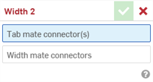
- Con el campo conectores de relación de pestaña resaltado, seleccione hasta dos conectores de relación. Pueden ser de la misma pieza o de diferentes piezas.
- Seleccione el campo Conectores de relación de ancho para resaltarlo y, luego, los dos conectores de relación de la misma pieza o de diferentes piezas. Los conectores de relación de ancho deben estar asociados a una o varias piezas diferentes a las de los conectores de relación de la pestaña.
- Haga clic en la marca de verificación (
 ) para aceptar la relación de ancho.
Las piezas asociadas a los conectores de relación de pestaña ahora se desplazan a lo largo de un plano centrado entre los dos conectores de relación de ancho. Los planos XY de los conectores de relación de pestaña permanecen simétricos entre sí en este plano centrado.
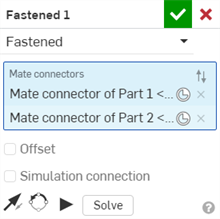
Una vez que se crea una relación entre dos conectores de relación explícitos o implícitos, puede editar cualquiera de los conectores de relación:
-
Abra el cuadro de diálogo Relacionar. A continuación, se utiliza la posición Relación cerrada como ejemplo. El proceso es similar para todas las relaciones, excepto para la Relación tangente, que no utiliza conectores de relación.
-
Haga clic en el ícono del conector de relación (
 ). Se abre el cuadro de diálogo del conector de relación, donde puede editar el tipo de origen, la entidad de origen, la alineación, la ubicación, la dirección del eje principal y la orientación del eje secundario del conector de relación:
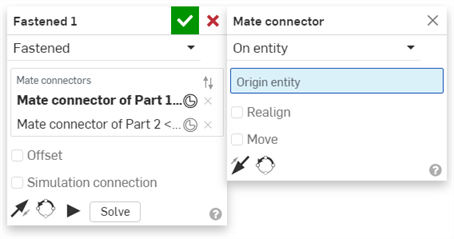
La edición de conectores de relación desde el cuadro de diálogo Relacionar se limita a los conectores implícitos o explícitos ubicados en el Ensamblaje actual. Los conectores de relación de Part Studios, subensamblajes o documentos vinculados deben editarse en su ubicación original.
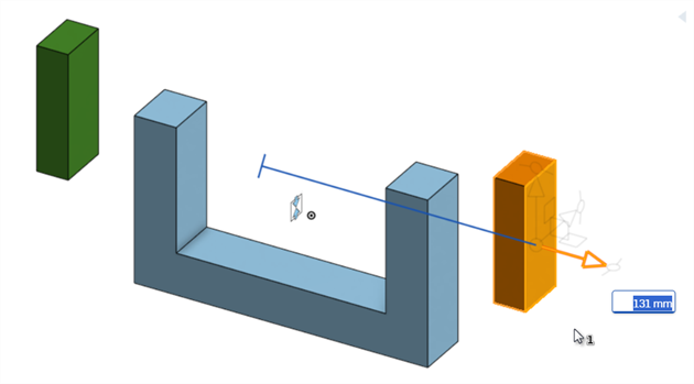
Conservación de una pieza simétrica entre dos conectores de relación de ancho.
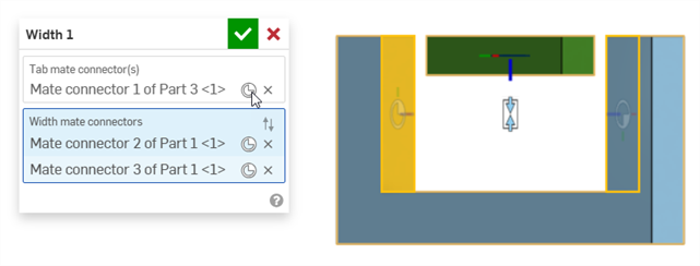
El rectángulo verde de la pieza 3 tiene un conector de relación en el medio de la pieza. La parte 1 azul en forma de U tiene conectores de relación de ancho en sus caras interiores.
-
La pieza 3 ahora es simétrica entre los 2 conectores de relación de ancho (las 2 caras interiores de la pieza 1).
-
La pieza 3 se puede desplazar o girar libremente a lo largo de su eje z. Cuando se traslada o gira la pieza 3 a lo largo de los ejes X o Y, se mueven ambas piezas.
Conservar la pieza 1 fija limita aún más el movimiento. Ahora, puede desplazar la pieza 3 libremente a lo largo de los ejes X y Z, pero no puede hacerlo a lo largo del eje Y. Puede girar la pieza 3 a lo largo del eje Z, pero no puede hacerlo alrededor de los ejes X o Y.
Conservación de una pieza simétrica entre dos conectores de relación de ancho
El rectángulo naranja de la pieza 2 y el rectángulo verde de la pieza 3 tienen conectores de relación en sus caras internas opuestas. La pieza 1 azul en forma de U tiene conectores de relación de ancho en sus caras interiores.
Cuando la pieza 2 o la 3 se desplazan a lo largo del eje z, permanecen simétricas entre sí y, cuando una se mueve, también lo hace la otra:
Cuando se desplaza la pieza 2 del rectángulo naranja, también se desplaza la pieza 3 del rectángulo verde, por lo que siempre permanecen simétricos, según sus conectores de relación.
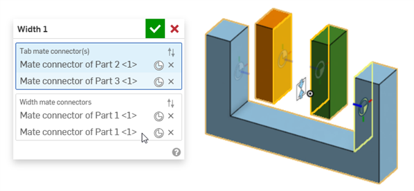
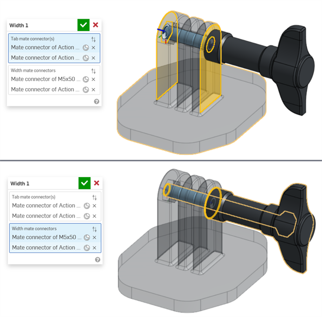
Uso de dos conexiones de relación de ancho para centrar entidades en una unión en U
En el ejemplo siguiente, se utilizan dos relaciones de acho para centrar un cuadro y un pasador en una junta en U.
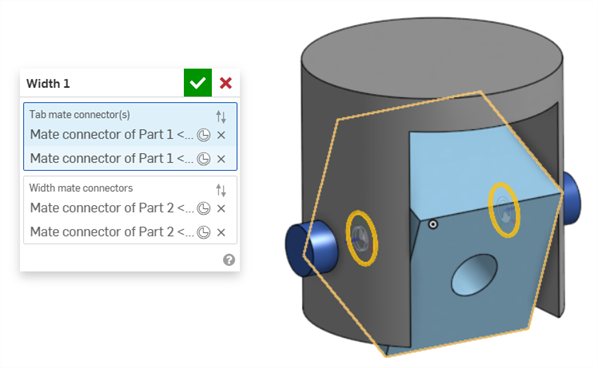
La relación de ancho se puede usar para centrar el cuadro en una unión en U, como se muestra a continuación. Los conectores de relación se colocan en ambos lados del cuadro (pieza 1) y se designan como los conectores de relación de la pestaña. Los conectores de relación se colocan en los dos lados interiores de la junta en U (pieza 2), que se designan como conectores de relación de ancho:
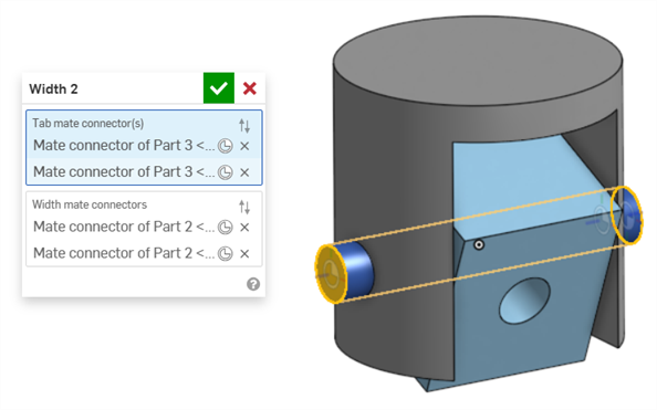
Se utiliza una segunda relación de ancho para centrar el cuadro en una junta en U. Los conectores de relación se colocan en ambos extremos del pasador (pieza 3), que se designan como los conectores de relación de la pestaña. Los mismos dos lados interiores de la junta en U (pieza 2) se designan como conectores de relación de ancho:
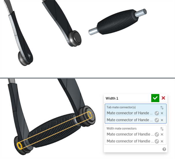
Centrado del eje del mango de un martillo neumático entre las tapas de extremo
En el ejemplo siguiente, se utiliza una relación de ancho para centrar el eje del mango de un martillo neumático entre las dos tapas de extremo de la empuñadura.
Los conectores de relación se colocan en ambos extremos del eje, que se designan como los conectores de relación de la pestaña. Los conectores de relación se colocan en las dos caras exteriores de las tapas de extremo, que se designan como conectores de relación de ancho:
Relación de ancho utilizada con una pieza asimétrica
En el ejemplo siguiente, se muestra cómo se puede utilizar la relación de ancho en una pieza asimétrica:
- Un conector de relación de pestaña y un conector de relación de ancho no pueden estar en la misma pieza.
- A diferencia de otras relaciones, se pueden usar dos conectores de relación en la misma pieza para los conectores de relación de la pestaña o los conectores de relación de ancho. Sin embargo, esto no es obligatorio.
- Se pueden seleccionar conectores de relación implícitos y explícitos en el cuadro de diálogo Relación ancho.
- Las relaciones de ancho no se pueden utilizar con las relaciones de posición.
- Haga clic en Mostrar relación de ancho en la Lista de operaciones de relación para ver la relación en el área gráfica.
La compatibilidad de la operación Relación de ancho con iOS y Android se limita a ver y editar las relaciones de ancho creadas en la plataforma de escritorio (navegador).