 Breitenverknüpfung
![]()
![]()
![]()
Verbinden Sie bis zu zwei Laschen, um sie symmetrisch zwischen zwei Verknüpfungsverbindungen beschränken. Auf der Langloch-Mittelebene sind Verschiebungen und eine normale Rotation zulässig. Die erste Auswahl definiert das Objekt, das zentriert werden soll. Die zweite Auswahl definiert die Mittelebene.
- Klicken Sie auf das Symbol für die Breitenverknüpfung (
 ).
). 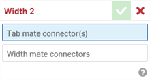
- Wählen Sie bei hervorgehobenem Feld Zungen-Verknüpfungsverbindung(en) bis zu zwei Verknüpfungsverbindungen aus. Diese können aus dem gleichen oder verschiedenen Bauteilen stammen.
- Wählen Sie das Feld Breiten-Verknüpfungsverbindungen aus, um es zu markieren. Wählen Sie die beiden Verknüpfungsverbindungen bei einem oder unterschiedlichen Bauteilen aus. Die Breiten-Verknüpfungsverbindungen müssen einem oder mehreren anderen Bauteilen zugeordnet sein als die Zungen-Verknüpfungsverbindungen.
- Klicken Sie auf das Häkchen (
 ), um die Breitenverknüpfung zu akzeptieren.
Die Bauteile, die den Zungen-Verknüpfungsverbindungen zugeordnet sind, werden jetzt entlang einer zentrierten Ebene zwischen den beiden Breiten-Verknüpfungsverbindungen verschoben und um diese gedreht. Die XY-Ebenen der Zungen-Verknüpfungsverbindungen bleiben auf dieser zentrierten Ebene symmetrisch zueinander.
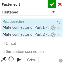
Sobald eine Verknüpfung zwischen zwei expliziten oder impliziten Verknüpfungsverbindungen erstellt wurde, können Sie jede Verknüpfungsverbindung bearbeiten:
-
Öffnen Sie das Dialogfenster „Verknüpfung“. Im folgenden Beispiel wird die feste Verknüpfung verwendet. Der Vorgang ist für alle Verknüpfungen ähnlich, mit Ausnahme der Tangentialverknüpfung, bei der keine Verknüpfungsverbindungen verwendet werden.
-
Klicken Sie auf das Symbol für Verknüpfungsverbindungen (
 ). Das Dialogfenster „Verknüpfungsverbindung“ wird geöffnet, in dem Sie den Ursprungstyp, das Ausgangsobjekt, die Ausrichtung, die Position, die Primärachsenrichtung sowie die Ausrichtung der Sekundärachse der Verknüpfungsverbindung bearbeiten können:
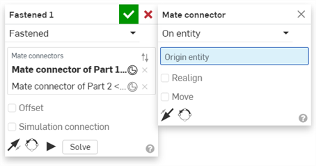
Das Bearbeiten von Verknüpfungsverbindungen im Dialogfenster „Verknüpfung“ ist auf implizite oder explizite Verbindungen beschränkt, die sich in der aktuellen Baugruppe befinden. Verknüpfungsverbindungen aus Part Studios, Unterbaugruppen oder verknüpften Dokumenten müssen an ihrer ursprünglichen Position bearbeitet werden.
Ein Bauteil zwischen zwei Breiten-Verknüpfungsverbindungen symmetrisch halten
Das grüne Rechteck Bauteil 3 hat eine Verknüpfungsverbindungen, die in der Mitte des Bauteils angeordnet ist. Das U-förmige blaue Bauteil 1 hat an seinen Innenflächen Breiten-Verknüpfungsverbindungen.
-
Das Bauteil 3 ist jetzt symmetrisch zwischen den beiden Breiten-Verknüpfungsverbindungen (den beiden Innenflächen von Bauteil 1).
-
Bauteil 3 kann frei entlang seiner Z-Achse verschoben oder gedreht werden. Durch Verschieben oder Drehen von Bauteil 3 entlang der X- oder Y-Achse werden beide Bauteile bewegt.
Wenn Bauteil 1 verankert wird, wird die Bewegung weiter beschränkt. Sie können Bauteil 3 jetzt frei entlang der X- und Z-Achse verschieben, aber nicht entlang der Y-Achse. Sie können Bauteil 3 entlang der Z-Achse rotieren, aber nicht um die X- oder Y-Achse.
Zwei Bauteile zwischen zwei Breiten-Verknüpfungsverbindungen symmetrisch halten
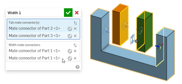
Das orangefarbene Rechteck-Bauteil 2 und das grüne Rechteck-Bauteil 3 haben Verknüpfungsverbindungen, die auf ihren gegenüberliegenden Innenflächen platziert sind. Das U-förmige blaue Bauteil 1 hat an seinen Innenflächen Breiten-Verknüpfungsverbindungen.
Wenn entweder Bauteil 2 oder Bauteil 3 entlang der Z-Achse verschoben werden, bleiben sie symmetrisch zueinander. Wenn dann das eine Bauteil bewegt wird, wird das andere ebenfalls bewegt:
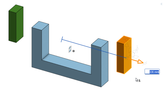
Beim Versetzen des orangefarbenen Rechteck-Bauteils 2 wird auch das grüne Rechteck Bauteil 3 versetzt, sodass sie immer symmetrisch bleiben, basierend auf ihren Verknüpfungsverbindungen.
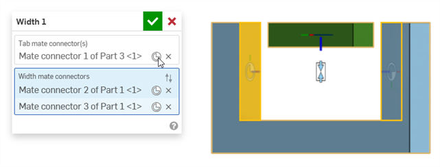
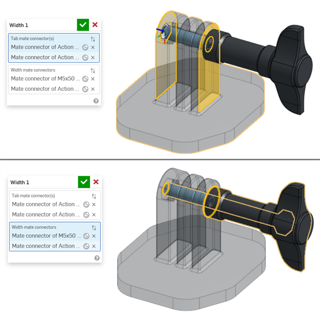
Breiten-Verknüpfungsverbindungen mit zwei Breiten zum Zentrieren von Objekten in einer U-Verbindung verwenden
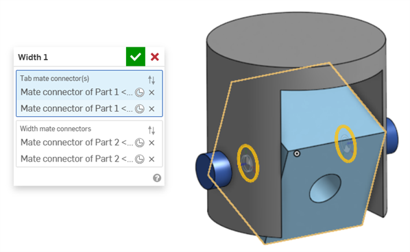
Im folgenden Beispiel werden zwei Breitenverknüpfungen verwendet, um einen Quader und einen Stift in einer U-Verbindung zu zentrieren.
Mit einer Breitenverknüpfung kann der Quader in einer U-Verbindung zentriert werden, wie unten gezeigt. An beiden Seiten des Quaders (Bauteil 1) befinden sich Verknüpfungsverbindungen, die so genannten Zungen-Verknüpfungsverbindungen. Die Verknüpfungsverbindungen sind an den beiden Innenseiten der U-Verbindung (Bauteil 2) platziert, den Breiten-Verknüpfungsverbindungen:
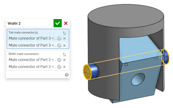
Eine zweite Breitenverknüpfung wird verwendet, um den Quader in einer U-Verbindung zu zentrieren. Verknüpfungsverbindungen werden an beiden Enden des Stifts (Bauteil 3) platziert, die als Zungen-Verknüpfungsverbindungen bezeichnet werden. Dieselben beiden Innenseiten der U-Verbindung (Bauteil 2) werden als Breiten-Verknüpfungsverbindungen bezeichnet:
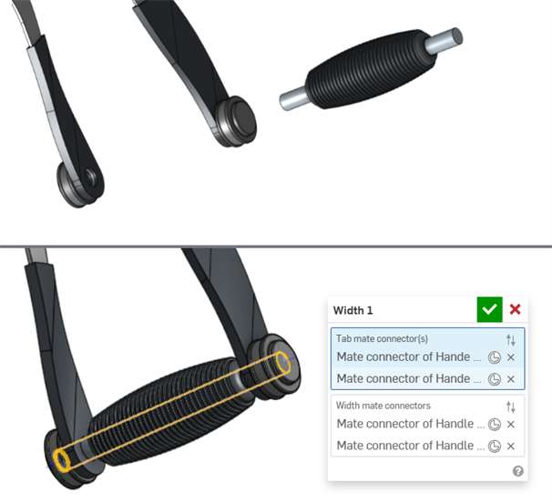
Presslufthammer-Griff zwischen seinen beiden Griffbefestigungen zentrieren
Im folgenden Beispiel wird eine Breitenverknüpfung verwendet, um den Griff eines Presslufthammers zwischen seinen beiden Griffbefestigungen zu zentrieren.
An beiden Griffenden befinden sich Verknüpfungsverbindungen, die Zungen-Verknüpfungsverbindungen. Die Verknüpfungsverbindungen werden auf den beiden Außenflächen der Griffbefestigungen platziert, den Breiten-Verknüpfungsverbindungen:
Breitenverknüpfung mit einem asymmetrischen Bauteil
Das folgende Beispiel zeigt, wie Sie eine Breitenverknüpfung für ein asymmetrisches Bauteil verwenden können:
- Eine Zungen-Verknüpfungsverbindung und eine Breiten-Verknüpfungsverbindung können sich am selben Bauteil befinden.
- Im Gegensatz zu anderen Verknüpfungen ist es möglich, zwei Verknüpfungsverbindungen am selben Bauteil entweder für die Zungen-Verknüpfungsverbindung(en) oder für die Breiten-Verknüpfungsverbindungen zu verwenden. Dies ist jedoch nicht nötig.
- Im Dialogfenster Breitenverknüpfung können sowohl implizite als auch explizite Verknüpfungsverbindungen ausgewählt werden.
- Breitenverknüpfungen können nicht mit Verknüpfungsbeziehungen verwendet werden.
- Klicken Sie in der Liste mit den Verknüpfungs-Features auf „Breitenverknüpfung anzeigen“, um die Verknüpfung im Grafikbereich zu sehen.
Die iOS- und Android-Unterstützung für das Feature „Breitenverknüpfung“ beschränkt sich auf das Anzeigen und Bearbeiten von Breitenverknüpfungen, die mit der Desktop-Version (Browser) erstellt wurden.