 Blech-Ausformung
![]()
![]()
![]()
Mit iOS und Android können Sie nur das Feature „Blech-Ausformung“ für Ausformungen anzeigen und bearbeiten, die zuvor mit der Desktop-Plattform (Browser) von Onshape erstellt wurden.
Verfügbar in: Part Studios
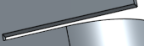
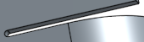
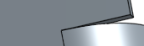
Erstellen Sie ein Blechbauteil als Übergang zwischen zwei Profilen.
So erstellen Sie eine Blech-Ausformung:
- Klicken Sie in einem Part Studio auf die Schaltfläche Blech-Ausformung (
 ).
).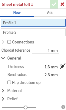
- Wählen Sie Neu aus, um ein neues Blechbauteil zu erstellen. Oder wählen Sie Hinzufügen aus, um die Ausformung zu einem vorhandenen Blechbauteil hinzuzufügen.
- Wählen Sie mit dem Fokus im Feld Profil 1 das Startprofil (Region, Fläche, Kante oder Punkt) aus.
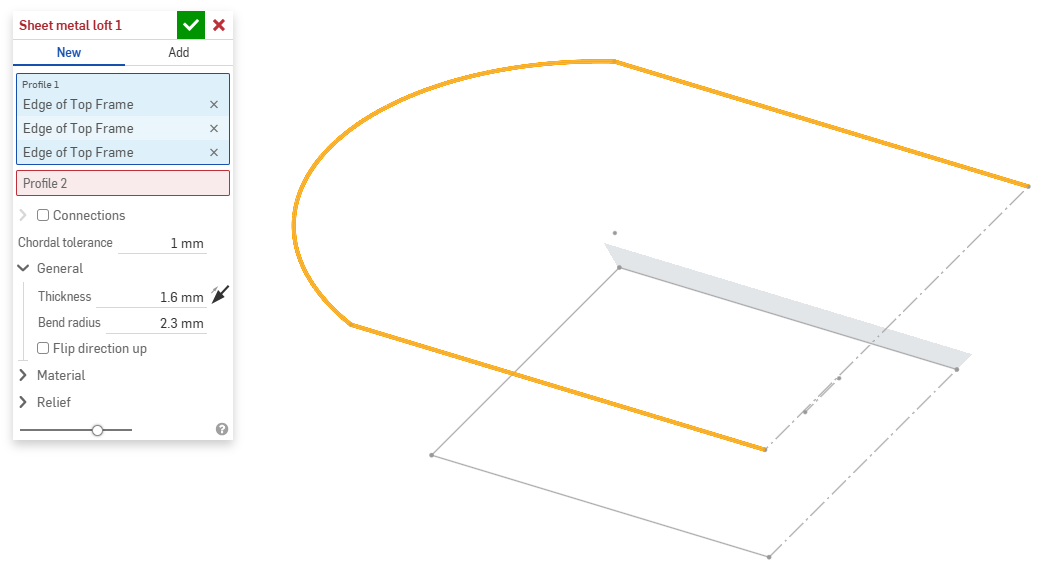
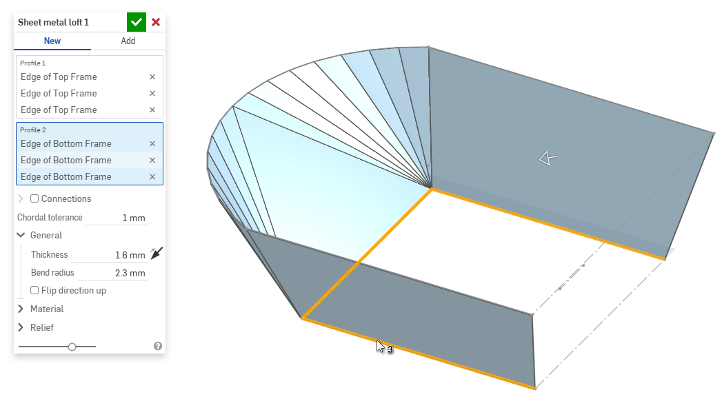
- Wählen Sie mit dem Fokus im Feld Profil 2 das Endprofil aus. Onshape erstellt ein Blechmodell zwischen den beiden Profilen.
- Klicken Sie auf das Kontrollkästchen Verbindungen, um das Verdrehen des resultierenden Modells besser kontrollieren zu können. Onshape schätzt die Nähe innerhalb der vorhandenen Scheitelpunkte/Kanten, falls keine Übereinstimmungen angegeben sind.
- Wählen Sie einen Scheitelpunkt oder eine Kante der Ausformung aus und ziehen Sie den oder die Manipulator(en), um die Verbindung anzupassen.
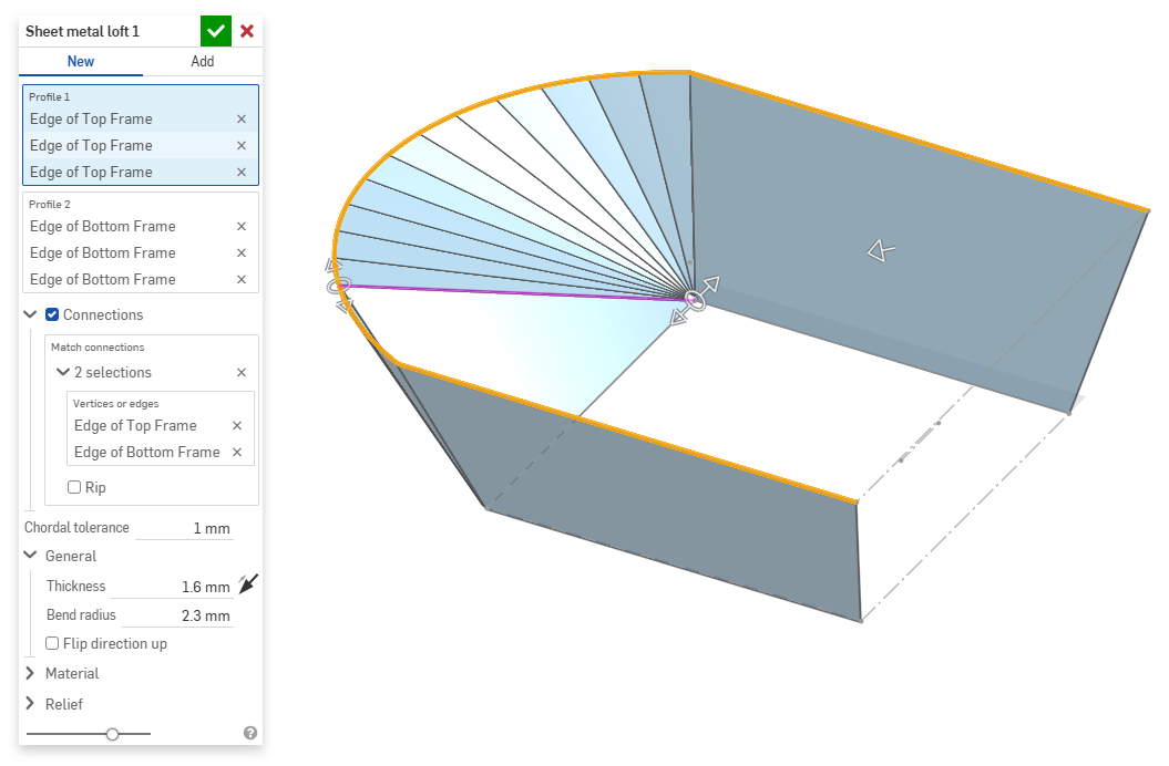
- Um das Modell an der Verbindung in einzelne Bauteile zu trennen, wählen Sie Schlitz aus.
- Wählen Sie einen Scheitelpunkt oder eine Kante der Ausformung aus und ziehen Sie den oder die Manipulator(en), um die Verbindung anzupassen.
- Verwenden Sie das Feld Sehnentoleranz, um den maximalen Abstand festzulegen, um den sich die tessellierte Geometrie von der darunter liegenden Oberfläche unterscheiden kann.
- Wenn Sie neue Blechmodelle erstellen, können Sie auch die folgenden Abschnitte erweitern, um das Modell weiter zu verfeinern:
- Allgemein:
- Dicke: die Dicke des Blechs. Klicken Sie auf den Pfeil, um die Richtung umzukehren.
- Biegeradius: der Innenradius der erzeugten Biegungen.
- Richtung nach oben umkehren: kehrt die Ausrichtung des Blechmodells und der flachen Ansicht um. Das ist praktisch, um festzulegen, ob Biegungen relativ zum Modell nach oben oder nach unten gerichtet sind.
- Material (die Optionen in diesem Abschnitt sind identisch mit denen beim Feature Blechmodell):
- Biegeberechnung: legt fest, wie die Biegungen berechnet werden. Es stehen folgende Optionen zur Verfügung:
- K-Faktor (Standard): verwendet das Verhältnis der neutralen Achse zur Materialstärke.
- Biegezuschuss: verwendet die Länge des neutralen Linienbogens zwischen den Tangentenpunkten einer Biegung.
- Biegeverkürzung: verwendet die Differenz zwischen der Summe der Flanschlängen (von der Kante bis zur Spitze) und der ursprünglichen flachen Länge.
Die hier gewählte Biegeberechnung wird als Spalte in der Blechtabelle verwendet. Jede Biegung kann individuell angepasst und direkt in der Tabelle bearbeitet werden. Siehe Blechtabelle und flache Ansicht.
- Standard-Biege-K-Faktor: der Bruchteil der Materialdicke, auf dem die neutrale Achse liegt. (Die Standardeinstellung ist 0,45.)
- Gerollter K-Faktor: der Bruchteil der Materialdicke, auf dem die neutrale Achse auf einem Bereich der Walzwand liegt. (Die Standardeinstellung ist 0,5.)
- Biegeberechnung: legt fest, wie die Biegungen berechnet werden. Es stehen folgende Optionen zur Verfügung:
- Freischnitt (die Optionen in diesem Abschnitt sind identisch mit denen beim Feature Blechmodell):
- Minimaler Abstand: der geringste Abstand zwischen Blechkanten, der einen Schlitz definiert.
- Ecken-Freischnitt-Typ:
- Quadrat – dimensioniert
Flache Ansicht:
 3D-Ansicht:
- Rechteck – skaliert
Flache Ansicht:
 3D-Ansicht:
- Rundung – dimensioniert
Flache Ansicht:
 3D-Ansicht:
- Rundung – skaliert
Flache Ansicht:
 3D-Ansicht:
- Closed
Flache Ansicht:
 3D-Ansicht:
- Einfach
Flache Ansicht:
 3D-Ansicht:
- Quadrat – dimensioniert
- Ecken-Freischnitt-Maßstab: der Maßstab der Eckenöffnung (für skalierte Öffnungen), ein Wert zwischen 1,00 und 2,00. Biegungs-Freischnitt-Typ: die Form des Biegungs-Freischnitts:
- Rechteck – skaliert
- Langloch – skaliert
- Riss
- Rechteck – skaliert
- Biegungs-Freischnitt-Tiefenmaßstab: ein Wert zwischen 1,00 und 5,00. Sobald Sie einen Wert eingegeben haben, wird er in allen Dokumenten zum Standard.
- Ein Wert von 1 führt zu einer Biegeentlastung, die die Biegung perfekt berührt. Eine rechteckige Biegeentlastung entspricht der Tiefe des Langlochs.
- Jeder Wert nach 1 fügt Tiefe hinzu. Dabei gilt die Formel:
(depth scale -1) * bendRadius
- Biegungs-Freischnitt-Breitenskalierung: Ein Wert zwischen 0,0625 und 2,00. Sobald Sie einen Wert eingegeben haben, wird er in allen Dokumenten zum Standard. Die Breite der Biegeentlastung wird nach folgender Formel berechnet:
thickness * width scale.
- Allgemein:
- Wenn Sie etwas zu einem vorhandenen Blechmodell hinzufügen, klicken Sie auf das Feld Zusammenführungsbereich und wählen Sie dann das Bauteil aus, dem Sie etwas hinzufügen möchten. Der Zusammenführungsbereich kann nur Körper eines einzelnen aktiven Blechmodells akzeptieren.
Wenn ein Blechmodell aktiv ist (während der Erstellung oder Bearbeitung), stehen zusätzliche Tools zur Verfügung:
-
 Flansch: Erstellen Sie eine Wand für jede ausgewählte Kante, die durch eine Biegung mit der ausgewählten Kante verbunden ist.
 -
 Blechkantenrand: Erstellen Sie auf einem vorhandenen Blechteil einen Blechkantenrand für jede ausgewählte Kante/Fläche.
 -
 Zunge: Fügen Sie eine Zunge zu einem Blechflansch hinzu.
 -
 Biegen: zum Biegen eines Blechmodells entlang einer Referenzlinie mit zusätzlichen Optionen zur Biegekontrolle.
 -
 Form: Erstellen Sie Form-Features auf vorhandenen Blechmodellen. Formen können aus dem aktuellen Dokument, anderen Dokumenten oder einer vordefinierten Bibliothek von Blechformen ausgewählt werden.
 -
Ausformung: Erstellen Sie Blechmodelle, die zwei Profile verbinden.
-
 Verbindung erstellen: Wandeln Sie die Schnittstelle von zwei Wänden in ein Verbindungs-Feature um, entweder in eine Biegung (Wände, die durch zylindrische Geometrie verbunden sind) oder in einen Schlitz (kleiner Spalt zwischen den beiden Wänden).
 -
 Ecke: Ändern Sie einen Eckentyp und den Freischnitt-Maßstab.
 -
 Biegungs-Freischnitt: Ändern Sie einen Biegungs-Freischnitt (den kleinen Schnitt am Berührungspunkt zwischen Biegungsende und freier Kante), die Tiefe und die Freischnitt-Breite.
 -
 Verbindung ändern: zum Ändern einer bestehenden Verbindung. Wandeln Sie zum Beispiel eine Biegung in eine Rippe um. Diese Option ist derzeit über die Abwicklungstabelle verfügbar.
 -
 Eckenfreistich: zum Ausbrechen einer Ecke bei Blechteilen, indem Sie eine Verrundung oder Fase anwenden. Wählen Sie eine Eckkante oder einen Eckpunkt aus und geben Sie die Art und den Abstand des Eckenfreistichs an. Es wird empfohlen, dieses Feature nach Fertigstellung aller Flansche und Verbindungen des Blechmodells zu verwenden.
 -
 Blechtabelle und flache Ansicht: zum Öffnen und Schließen der Schlitz-/Biegungs-Tabellen und Visualisierung des Modells für die Blechabwicklung. Verwenden Sie diese Tabelle, um die Schlitze in Biegungen und die Biegungen in Schlitze umzuwandeln.
 -
 Blechmodell fertigstellen: schließt (deaktiviert) das Blechmodell. Erstellt ein Feature in der Feature-Liste.