 Ruled Surface
![]()
Create a new or additional ruled surface from an existing edge or multiple edges of a sketch region.
In the Feature toolbar:
![]()
Create a new or additional ruled surface from an existing edge or multiple edges of a sketch region.
The Ruled surface feature allows you to add or create a new Ruled surface from an existing edge or multiple edges of a sketch, surface, or part.
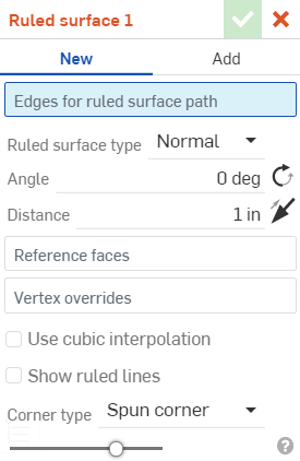
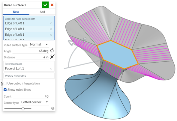
Click the Ruled surface feature from the feature toolbar. Select the edges for the ruled surface path. Here, all the edges of the polygon are selected.
You can select different ruled surface types: Normal, Tangent, Aligned with direction, or Angle from direction. Specify the Angle for the ruled surface, and click the rotation icon to reverse the direction. Specify the Distance, and click the direction arrow to reverse the direction. In this case the direction cannot be reversed and so you will see a red outline to indicate this is an error.
You can also add Vertex overrides. Select a point and create an angle and direction from that point. Add as many Vertex overrides as required.
Check Use cubic interpolation to create a finer continuity between the segments of the surface. Check Show ruled lines adds lines to the ruled surface. Values are set from 1 to 100, with 40 being the default.
Select a corner type. Spun corner is the default. Extended corner extends the corners to create a straight edge, if possible. Lofted corner produce slightly lofted corners, and No corner removes corners.
Steps
- Click
 .
.
- Select the Edges for the ruled surface path. This can be a single edge or multiple edges.
- Specify the Ruled surface type.
- Normal - The surface is normal to the edge.
- Tangent - The surface is tangent to the edge.
- Aligned with direction - The surface is aligned to an alternate direction; for example, a ruled surface aligned to construction geometry or the edge of another object.
- Angled from direction - The surface is angled from a selected direction; for example, a ruled surface angled to the direction of construction geometry or another object.
- Specify the Angle for the surface, in relation to the selected edge(s), in degrees. Click the rotation icon to reverse the angle.
- Specify the Distance from the edge(s). Click on the arrow icon to reverse the direction.
- (Optional) Select a Reference face. This is the face used as a reference for the Ruled surface. When an edge is first selected for the Ruled surface path, one of its adjacent faces is used as the edge's reference face and is automatically added to the dialog. To select a different or additional reference face (for example, the edge's opposing face), you can select the Reference faces area of the dialog and then select the new Reference face. To delete the previously selected Reference face, click the x icon to the right of the face label.
- (Optional) select
Vertex overrides. By default, the overall ruled surface definition is governed by the path created by the selected edge(s). However, you can override this behaviour and specify the ruled surface definition at any selected point, or multiple points. Select the Vertex overrides area of the dialog, and then select a vertex along the ruled surface path. You can then specify the following, for each Vertex override:
- Ruled surface type
- Normal, Tangent, Aligned with direction, or Up to vertex. These are similar to the Ruled surface type above, but with the additional Up to vertex option - Up to a selected point (vertex) or mate connector (inferred or existing). Click the
 in order to select inferred Mate connectors. Once a Mate connector is selected, click the Mate connector icon in the dialog field to open a dialog with which to edit the Mate connector.
- Angle - Corner angle, in degrees. Click the rotation icon to reverse the angle.
- Distance - Corner distance. Click on the arrow icon to reverse the direction.
- Ruled surface type
- Normal, Tangent, Aligned with direction, or Up to vertex. These are similar to the Ruled surface type above, but with the additional Up to vertex option - Up to a selected point (vertex) or mate connector (inferred or existing). Click the
- (Optional)
Use cubic interpolation
- By default, the Ruled surface path uses linear interpolation. For finer continuity between the segments, you can select the cubic interpolation option.

An example of linear (left) and cubic (right) interpolation between two mirrored ruled surface segments.
- (Optional) Show ruled lines - Displays ruled lines on all Ruled surfaces. The ruled lines are set per continuous path. The count can be set from 1 to 100, with 40 as a default.
- Select the
Corner type. Options are:
- Spun corner (default) - Uses curved spun corners to connect adjacent surface edges, if possible.
- Extended corner - Uses extended surface lines to connect adjacent surface edges, if possible.
- Loft corner - Uses loft corners to connect adjacent surface edges, if possible.
- No corner - Omits corners between adjacent surfaces edges.
-
Click
 .
.
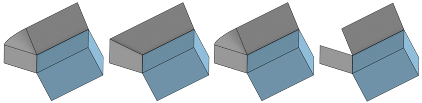
From left to right: Normal, Tangent, Aligned with direction, and Angled from direction.
If you select a direction from which a part or whole of the ruled surface cannot be created, the direction is shown in red within the sketch, indicating it is in error. Select a new direction edge for your alignment.
If you select an angle or distance which forces the ruled surfaces to cross into each other, an error is created, and the surface is not visible. The ruled surface displays in red at the top of the Ruled surface dialog and in the Features list.
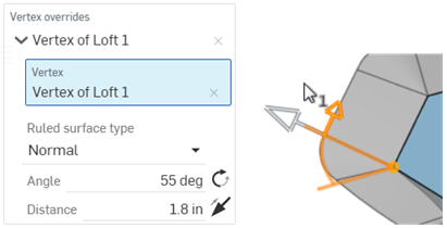
A Vertex override applied, whereby the vertex is used to manipulate the Ruled surface angle and direction.
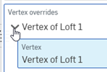
Each Vertex Override can be collapsed or expanded using the dropdown arrow to the left of the Override label.
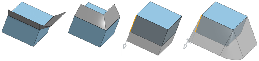
From left to right: Spun, Extended, Loft, and No corners.
If corners cannot be created between surface edges, an error is generated and a message is displayed:

A Ruled surface extended outward from a polygon surface