![]()
![]()
![]()
![]()
There are three ways to create a drawing:
- Using a part, surface, Assembly, or Part Studio (presented below)
- As an empty drawing, from scratch
- By importing a .DWG or .DXF file
Navigating within drawings can be customized to accommodate your familiarity with some traditional CAD systems. See Setting Preferences for more information.
Basic workflow
- Create a drawing of a part, curve, or surface in a Part Studio, or of a subassembly in the Assembly list:
- Right-click on the name of the part, curve, or surface in the Part list or assembly in the Assembly list.
- Select Create drawing of <name>.
- Choose a template.
Notice that you can select from Onshape-supplied templates, by selecting the Onshape filter on the left (or Show Onshape drawing templates).
If you are a member of a company or a team, those filters are in the list as well (as the company or team name) under Existing templates.
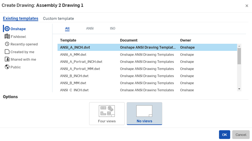
You are also able to create your own custom templates.
- Click OK.
For more details on creating drawings, see Creating a Drawing.
- Createviews. The drawing is created, by default, with no views but with a view at your cursor. Use the Escape key to cancel the view, or click to place it in the drawing. You can also create additional views.
- Add dimensions:
- Select a dimension tool.
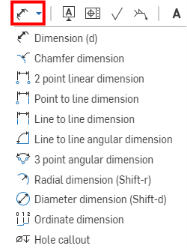
Notice that some of the tool icons have open circles; these tools use snap points, the other tools use edges.
- Snap points appear as open boxes: hover and then click when the appropriate snap points are visible (or select necessary edges).
The dimension text box appears on the click of the second snap point or edge.
- Drag dimension text box to desired location and click to place.
For more details, see Dimensions.
- Select a dimension tool.
- Export to .DXF, .DWG, or PDF:
- Right-click on the drawing tab.
- Select the preferred format.
Access the downloaded file on your local drive.
- Print the file:
- Open the downloaded file in a compatible application.
- Print the file.
All drawings objects (except view geometry) have context menus: right-click on an object to access the context menu. These menus vary with the type of object.
It is worth noting that the cursor will change depending upon what type of selection a command requires. The two types of cursors you will see when working with drawings are:
-
 - Indicates a requirement to select a position
-
 - Indicates a requirement to select an entity
The grip points that appear on drawings entities indicate how you can use them. Circular grip points can be used to move an entity. Square grip points can be used to resize an entity. Red grip points indicate an error. More details are shown in the table below:
| Grip point type | Hover | Selected | Cursor |
|---|---|---|---|
|
Normal resize |

|

|

|
| Rotate: Drag these to rotate |

|

|

|
| Flip: Click these to flip the orientation |

|

|

|
| Point attachment: Drag these to reattach to another point |

|
|

|
| Edge attachment: Drag these to reattach to another edge |

|
|

|
| Dimension text: The entire dimension is dragable, no grip points are necessary |

|

|

|
Inferencing and snap points
Callouts and dimensions in Onshape drawings have automatic inferencing between each other upon creation and before placement in the drawing. Turn off inferencing by holding the Shift key during the operation, if you wish.
Callout inferencing and snapping behavior
Dimension inferencing and snapping behavior
Once placed, there is no association among entities; each entity can be dragged on its own, even after snapping alignment.
Copying and pasting a view
See Copying a view.
Copying and pasting drawing entities
Certain entities in drawings are able to be copied and pasted for ease of duplication. These entities may then be tweaked for changes, instead of creating similar constructs from scratch. These entities are:
- Notes
- GDT frames
- Datum
- Hole callout dimensions
- BOM tables
- Surface finish symbols
- Weld symbols
- Balloons
- Tables
To duplicate these entities:
- Hover the cursor over the entity; it will show in highlighting.
- Use the Alt key and the LMB (left mouse button); the cursor will show a + indication.
- Continue to hold down the Alt key and LMB and drag the entity to the desired location.
- Release the mouse button to place the entity.
- Repeat as desired.