Creating a Sketch
The estimated time of completion is 4 minutes
This section covers how to begin creating a sketch in an Onshape document.
The basic container in Onshape differs from the files of other CAD systems. Onshape uses a structure we call a document, and documents can hold all types of CAD data and supporting materials like images, files, PDFs and more.
To begin creating a sketch in Onshape, you first create a Document.
Navigate to your enterprise URL or to https://cad.onshape.com/signin and enter your user credentials.
Create a document
Onshape documents can contain as many tabs as needed, of any type needed. You can create more, delete, even copy tabs. Right-click on a tab to access its context menu.
Think of Onshape documents as multi-data containers. Not only can you sketch, create parts, assemble parts, and create drawings all in one document, but you are also able to store non-CAD data in any document as well: images, non-translated CAD data, PDFs and more. Just about any type of file you want to keep track of has the ability to be imported into a document.
- On the Documents page, the page that appears when you sign in to your account, click Create.
- Select Document... from the menu.
- Type a name in the Document name field (eg. "Primer").
- Click OK.
The document opens and contains two tabs: Part Studio 1 and Assembly 1. Tabs are Onshape's way of allowing you to store more than one type of data together in one place. Look toward the bottom of the window to see the name of the tab. Click a tab to activate it. Each data type is stored in a specific tab type.
Create a sketch
- Onshape dialogs all have the same anatomy: fields to fill out, selections to make, and a check mark to click to save the actions you take. (Click the red x to close the dialog without saving any actions.)
- Onshape tools all work the same way; click the tool icon to activate the tool, click again to deactivate. Tools remain selected until you toggle them off: press the tool shortcut key, the Escape key, or click the icon in the toolbar.
- When selecting entities in the graphics area, Onshape outlines or highlights entities upon hover when they are selectable for the current action.
- Access the keyboard shortcut map through the Help menu.
- The first dimension you apply scales the entire sketch.
Onshape parts typically begin with a sketch. The first tool on the Part Studio toolbar is Sketch (to the right of the Undo/Redo icons).
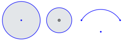
To create a solid, you need a sketch with closed regions (as opposed to creating a surface, for which only a sketch curve is necessary). Onshape automatically shades all closed regions of a sketch. Below are examples of closed regions and sketch curves:
- Click Sketch.
- The dialog opens:
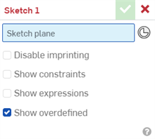
Blue highlighted fields indicate selection in the graphics area is needed
- Select a plane in the graphics area or from the Features list on the left.
- Press the N key to orient the sketch plane to normal.
- Click
 (or press the G key) to select the Rectangle tool.
 - Click in the graphics area to start the rectangle, move the cursor to draw the rectangle.
- When the rectangle is the proper size and proportion (estimated), click to set the rectangle.
Dimension boxes appear along the height and width of the rectangle.
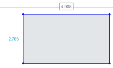
- Type 4 for the width and press Enter. The height box immediately becomes active. Type 3 for the height and press Enter. (You can edit or delete these dimensions at any time, when the sketch dialog is open.)
- Click to begin another rectangle. Click to set the size of the second rectangle.
- Type 1.5 for the width and press Enter. Type 3.2 for the height and press Enter.
- Press the Escape key to release (deactivate) the Rectangle tool.
- Click the check mark in the dialog to accept the actions and close the dialog (to create and save the sketch).
Since the default units were defined previously, units need only be entered if they are different from the default.
If you accidentally click the red x and cancel the sketch, you have ten seconds to click Restore in the blue message at the top of the window to restore the sketch.
Notice the sketch is listed in the Features list on the left (as Sketch 1).
Selecting a tool
Hover over a tool icon in the toolbar for information. A short hover displays the tool name. A long hover displays a short explanation of how to use the tool.
Parts are created from sketches and your design goals dictate what Feature tools you use to create a part. In general, you will start with the first group in the Feature toolbar (visible in a Part Studio whenever no sketch dialog is open):
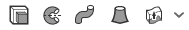
These tools are, from left to right: Extrude, Revolve, Sweep, Loft, and Thicken. The down arrow beside Thicken reveals an additional tool, Enclose.
Click a tool to select it. Click again to deselect it (or press the Escape key).
Create a part from the sketch
All sketches, features, and part in the lists on the left can be renamed. Right-click on the name in the Feature or Parts list to access the context menu for an item.
Parts (solid bodies) are created from sketch regions (closed regions are indicated by shading). Surfaces can be created from any sketch curves, even if they are part of a closed region.
- Select the Extrude tool
 in the toolbar.
The dialog opens.
- Select the enclosed (shaded) regions of both rectangles.
- Accept the defaults for the remaining fields in the dialog.
- Click the check mark to accept the actions and close the dialog.
Notice the parts are listed in the Parts list on the left (Part 1 and Part 2).
- Press the P key to hide planes and show planes in the graphics area.
- Press the N key to orient the active plane to normal.
- Press Escape to turn off/deactivate selected tools.
- Press Enter to accept actions and close a dialog once required information is entered.
- Select the Extrude or Revolve tool with a sketch dialog open and Onshape automatically selects all enclosed regions, including nested regions:
- Drag the manipulator arrow for pulling material when creating parts (example shown below).
- Use the direction arrows
 in a dialog (when available) to change the direction of the action (example shown below in the Extrude dialog).
For additional Learning center resources, follow the self-paced courses here: Introduction to Sketching (Onshape account required) and Introduction to Part Design (Onshape account required).